SINVERT 350, SINVERT 420 and SINVERT 500 TL Operating Instructions – 11/2009 SINVERT Answers for environment.
Introduction 1 Description 2 Application 3 Installation 4 Support 5 SINVERT SINVERT 350, SINVERT 420 and SINVERT 500 TL Operating Instructions Edition 11/2009
Safety instructions These Operating Instructions contain information which you should observe to ensure your own personal safety as well as to protect the product and connected equipment. The notices referring to your personal safety are highlighted in the manual by a safety alert symbol. Notices referring only to equipment damage have no safety alert symbol. Warnings are shown in descending order according to the degree of danger as follows.
Contents 1 Introduction ........................................................................................................ 8 1.1 About this documentation............................................................................ 8 1.1.1 1.1.2 1.1.3 2 Description ....................................................................................................... 10 2.1 3 Scope of validity ...................................................................................... 8 Target group ...
4.4 4.4.1 4.4.2 5 Communication ......................................................................................... 57 Profibus ................................................................................................. 58 RS422/Ethernet ..................................................................................... 59 Support ............................................................................................................. 60 5.1 Contact addresses ...........................
Figures Figure 2-1 Overview of PV system ............................................................................. 10 Figure 2-2 SINVERT 420 M ......................................................................................... 11 Figure 2-3 SINVERT 420 M with doors opened .......................................................... 11 Figure 2-4 SINVERT 500 TL ........................................................................................ 11 Figure 3-1 Example of inverter configuration ....
Figure 4-2 Screwing together transportation units.................................................... 43 Figure 4-3 Accessory kit ferrite rings.......................................................................... 48 Figure 4-4 Cable connection inverter – drive............................................................. 49 Figure 4-5 Position Cable connection inverter – DC link ............................................ 50 Figure 4-6 Cable connection inverter – DC link................................
Introduction 1.1 About this documentation 1 Introduction 1.1 About this documentation This manual will provide you with guidance in the use of SINVERT PV inverters. It provides you with a detailed overview of all the information you need to know about SINVERT PV inverters. We have checked that the contents of this document correspond to the hardware and software described. However, since deviations cannot be precluded entirely, we cannot guarantee full consistency.
Introduction 1.1 About this documentation 1.1.2 Target group This documentation contains information of interest to the following target groups: • • • Installation personnel Commissioning personnel Service personnel 1.1.
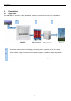
Description 2.1 Application 2 Description 2.1 Application The SINVERT PV inverter is a fully assembled, ready-to-connect inverter unit for PV installations. 1 2 3 Figure 2-1 Overview of PV system 1 The inverter transforms the DC voltage produced by the PV modules into an AC voltage. 2 The AC output voltage is transformed to the grid voltage by a medium-voltage transformer. 3 The PV solar system can thus be connected to the medium-voltage grid.
Description 2.
Application 3.1 Scope of delivery 3 Application 3.1 Scope of delivery The scope of delivery includes: • Inverter cabinet with • PROFIBUS cable, 1x10 mm diameter • RS422 cable, 1x10 mm diameter • Circuit manual • Operating Instructions • Operating Manual • PP solar CD • Ferrite • Mounting set for cabinet connection • Accessory kit with • DC link cable with M12 cable lug, diameter approx.
Application 3.2 Dimensions and weights 3.
Application 3.3 Configuration of the inverters 3.
Application 3.
Application 3.4 Medium-voltage components 3.
Application 3.4 Medium-voltage components Figure 3-6 Pressure relief for medium-voltage switchgear Covers for pressure relief openings and associated air channels, expanded metal grids, etc., are not part of the switchgear and shall be provided by the customer. The dimensions of the room and the necessary pressure relief openings depend on the type of switchgear and the amount of short-circuit current.
Application 3.5 Footprint 3.
Application 3.6 Installation requirements 3.6 Installation requirements The base of the inverter station must have sufficient capacity to carry the weight of the inverter. The inverter station must be designed for the wind and snow loads present at the installation site. The inverter cabinets can be placed close to walls. An air gap of at least 20 mm is required. To ensure adequate ventilation, the necessary distance to the ceiling must be maintained. A minimum distance of 400 mm must be observed.
Application 3.7 Ambient conditions 3.7 Ambient conditions 3.7.1 Storage Table 3-4 Ambient conditions for storage 3.7.2 Ambient temperature -25 °C to 70 °C Relative humidity ≤85%, non-condensing Transport Table 3-5 Ambient conditions for transport Ambient temperature -25 °C to 70 °C Relative humidity ≤85%, non-condensing 3.7.
Application 3.8 Cooling air inlet 3.8 Cooling air inlet The inverters must be provided with cooling air through the floor. The required floor cutouts for an inverter are shown in the following diagram: Figure 3-8 Cooling air inlet cutouts for SINVERT 350, 420, or 500 TL CAUTION Danger of mechanical damage Inverters with low-voltage transformers must be provided with cooling air through the floor. Insufficient cooling will lead to mechanical damage.
Application 3.9 Cooling air flow for inverters 3.9 Cooling air flow for inverters For air intake from below, the inverter must be installed above an open lower floor (cooling air inflow and cable entry from below). The requirements for cooling air are: Each SINVERT 350 requires 5400 m³ per hour at a temperature of max. 40 °C. Each SINVERT 420 requires 6,000 m³ per hour at a temperature of max. 40 °C. Each SINVERT 500 TL requires 4,800 m³ per hour at a temperature of max. 40 °C.
Application 3.
Application 3.10 Cable entry 3.10 Cable entry The required cable entries for an inverter are: • 8 x 95-300 mm² single core; four DC 250 A inputs • 8 x 300 mm² single core; AC outputs L1,L2,L3 + PEN 630 A (if the medium-voltage transformer is not located in a container) • Communications cable (according to the desired communications options) All cables must be suitable for outdoor use.
Application 3.11 Grounding and lightning protection 3.11 Grounding and lightning protection Building lightning strike protection is described in IEC 62305-3 (EN 62305-3). Among other things, this standard establishes the classification of individual lightning strike protection systems and indicates the resulting lightning strike protection measures required. Grounding and lightning strike protection are to be set up in conformance with IEC62305. 3.11.
Application 3.11 Grounding and lightning protection 3.11.2 Lightning protection A lightning protection system consists of an external lightning protection system and an internal lightning protection system. Using appropriate external lightning protection, the effect of a direct lightning strike into a building can be mitigated in a controlled way, and the lightning current can be discharged into the ground.
Application 3.12 Delivery of the inverters 3.12 Delivery of the inverters Please check that the consignment is complete against the accompanying dispatch documentation. If any items are missing from the consignment, please notify the relevant contact person immediately.
Application 3.13 Storage 3.13 Storage For the storage of the inverter units, the following conditions must be strictly observed. • • The inverters are intended for indoor installation in a clean and dry environment. They must be protected against temperature extremes (min. 25°C and max. 70°C) and excessive humidity (max. 85%).
Application 3.14 Shipping 3.14 Shipping In the following sections, note the following: • "Transportation unit" refers to the converter cabinet before it has been unpacked; • "Cabinet" refers to the converter cabinet after it has been unpacked A SINVERT 350, 420, or 500 TL inverter is delivered in two transportation units. The first transportation unit consists of a DC and drive cabinet, made up of two cabinets screwed together. The second transportation unit is the AC cabinet.
Application 3.14 Shipping Before moving the converter boxes to their final installation site, it is recommended that the cable for the DC input and the AC main power connection are first routed and prepared. Since the cables are very rigid, moving and connecting them after cabinet installation can be very difficult. The inverter cabinets are mounted on transport pallets as standard. They can thus be moved by forklift or pallet truck.
Application 3.14 Shipping 3.14.1 General safety guidelines Pay attention to the safety-related instructions in this section and on the packaging for: • transport • storage • proper handling In this way you will prevent personal injury and material damage. Particular care must be taken during transportation and handling to ensure that no components are bent and/or no alterations made to isolating distances.
Application 3.14 Shipping Tipping the cabinet too far can cause it to topple over and may damage the transport pallet (see figure 33). Tipping the cabinet may cause serious personal injury or substantial material damage. It is therefore essential that you read and carefully follow the safety notice below: WARNING Risk to life! Tipping! A cabinet, whether with or without pallet, must never be tipped in any direction. The cabinet is very heavy.
Application 3.14 Shipping 3.14.2 Center of gravity marking The transport unit/cabinet is heavy. The center of gravity is in the upper half of the cabinet. This can cause the device to topple over. The weight distribution is indicated directly on the inverter (see figure 3-5) by the center of gravity marking in accordance with ISO 780/symbol 7.
Application 3.15 Moving the cabinets 3.15 Moving the cabinets The transport unit/cabinet should be transported with extreme care. Driving over bumps should be avoided whenever possible. It should be noted that force is exerted via the pallet during transport and in positioning the transportation unit on the forklift. When using a crane, the allowable transport weight and the center of gravity should be observed.
Application 3.15 Moving the cabinets 3.15.1 Lifting the DC and drive cabinet The combined DC and drive cabinet can be lifted completely using a crane. To do this, the crane can easily grasp the provided transport plates on the top of the cabinet. The transportation unit must not swing or tip over.
Application 3.15 Moving the cabinets Figure 3-21 Transport by forklift Figure 3-22 Impermissible transport by forklift: Loading from the front side WARNING Use of an appropriate forklift If the forks are too short, the transportation unit/cabinet can tip over, which can lead to accidents resulting in death, serious injury, or damage to the cabinet. The forks of the truck must protrude at the rear of the transport pallet. The weight should not be lifted with the floor boards of the transportation units.
Application 3.15 Moving the cabinets 3.15.2 Lifting the SINVERT 350 and SINVERT 420 AC cabinet If the AC cabinet is to be lifted with a crane, a special crane hook must be used, or the crane must be mounted directly on the transformer. The AC cabinet housing cannot support the weight of the transformer. The special hook must be able to lift a weight of 1,800 kg.
Application 3.15 Moving the cabinets 3.15.3 Lifting the SINVERT 500 TL AC cabinet The SINVERT 500 TL AC cabinet can be lifted with a crane. To do so, the crane should be attached to the transport plates on the top side of the cabinet. The cabinet must not be allowed to swing or tip over. Further information can be found in the operating instructions for the AC and drive cabinets.
Application 3.15 Moving the cabinets 3.15.4 Lifting the cabinet off the transport pallet The cabinets are attached to the pallet by means of transport locks (upward-facing screws). To lift the cabinets off the pallet, you first need to undo the screw nuts. To slide the cabinets off the pallet, you need to push the screws out downwards far enough (e.g. using a hammer and a thick nail), so that the surface of the pallet becomes smooth.
Application 3.15 Moving the cabinets Use a crowbar to lift the cabinet so that you can place the rollers under the frame. If you want to change the rolling direction, you must lift the cabinet again, turn the rollers by 90° and place them under the frame again. You may need to strengthen the floor (with metal sheets) before you move the cabinets over it. Make sure that the metal sheets are placed such that you will be able to remove them again once the inverters have been installed.
Installation 4.1 Installation requirements 4 Installation 4.1 Installation requirements To ensure the installation of the inverter under the right environmental conditions, the following guidelines must be adhered to. The inverters are designed with IP20 protection. This means: • They are protected against the ingress of solid foreign bodies with a size of ≥ 12.5 mm. • They are not protected against the ingress of water. • They are intended for installation in indoor areas.
Installation 4.2 Mechanical installation 4.2 Mechanical installation CAUTION Danger of mechanical damage The forces occurring during transport may exert mechanical pressure on the components. This can cause damage to the device. • • The cabinets must be precisely aligned in a row to avoid shearing forces when the bases are attached with screws. Ensure that the installation area for the inverters is completely flat.
Installation 4.2 Mechanical installation 4.2.1 Screwing the transport units together When the cabinets have been placed in their final position, the DC and drive cabinets must be screwed together.
Installation 4.2 Mechanical installation 4.2.2 Bolting the cabinets to the floor Information on the attachment holes can be found in the floor plan. Each cabinet has four holes through which it can be bolted to the floor. The mounting dimensions are shown on the dimensional drawings. The open space between the top of the inverter cabinet and the ceiling is also set out in this installation guide.
Installation 4.3 Electrical installation 4.3 Electrical installation Installation of cables Cables that can cause disruptions or are themselves vulnerable to disruption, must be moved as far apart from each other as possible. The resistance to errors is improved by installing the cables close to the ground potential. Therefore, you should move these cables to corners and the ground surface. Unused wires should be grounded at least at one end. Low-voltage cables are divided into at least four classes.
Installation 4.3 Electrical installation 4.3.1 Observe the five safety rules For your personal safety and to avoid damage, the following safety instructions and all safety-relevant guidelines in the product documentation must be observed. In particular, the safety instructions attached to the product itself and the "Safety Instructions" chapter in all instruction manuals must be followed.
Installation 4.3 Electrical installation 4.3.2 External cable connections The following cable connections should be made: Table 4-1 External cable connections Cable connection Cross-section Tightening torque Screw type DC input 4x2x95-300 mm2 32 Nm M10 AC connection (L1, L2, L3, PEN) 3x2x240 mm2 70 Nm M12 DC link (only for master/slave combination) 2x2x240 mm2 70 Nm M12 Grounding min. 16 mm2 25 Nm M8 AC auxiliary power supply (optional) 4 mm2 0.
Installation 4.3 Electrical installation 4.3.3 Connecting the power cables and control cables Remove all fuses for the AC main power supply to the inverter, remove all the fuses from the DC inputs, and disconnect all the auxiliary circuits in the inverter cabinet. Remove all fuses and disconnect the auxiliary circuits in the AC distribution cabinet (if present). Before connecting, ensure that the cables are without power (isolated).
Installation 4.
Installation 4.3 Electrical installation Connection inverter – DC link In a master/slave combination, connect the DC link to the supplied cables (240 mm², single-core). Each connection is made using two parallel cables for each polarity, thus forming a ring. Ensure the correct polarity. Ensure that the screws are tight and the cable has sufficient strain relief.
Installation 4.3 Electrical installation CAUTION The configuration of the inverters according to chapter 3.3 should be taken into account for the length of the cables.
Installation 4.3 Electrical installation AC main power supply Connect the AC cables (going towards the MS transformer) and the PEN conductor. Ensure that the phase sequence is correct (clockwise). Ensure that the screws are tight and the cable has sufficient strain relief.
Installation 4.3 Electrical installation AC auxiliary power (self/external supply) The SINVERT 350/420 inverters have a self-supply option (delivery state). The jumpers on the terminal strip –OPT are set as shown.
Installation 4.
Installation 4.3 Electrical installation DC input Connect the DC cables (corresponding to the connection drawings and the cable list). Ensure the correct polarity. Ensure that the screws are tight and the cable has sufficient strain relief.
Installation 4.3 Electrical installation Internal control cable Plug in the connector in the AC cabinet (for the control cable coming from the drive cabinet). Control cable in the drive cabinet Connected control cable Figure 4-16 Connection of the control cables Grounding Ensure equipotential bonding between the cabinets that are not screwed together (between master and slaves). Use a single-core, yellow-green cable with a cross section of min.
Installation 4.4 Communication 4.4 Communication Communications cables and sensors should be connected only by people with the appropriate electrical training. Route communications and signal cables (Profibus, MPI, PPsolar, weather station, COM, LAN, telephone) separately (and far away) from power cables. Power cables should cross only at right angles. To the extent possible, you should run these cables along the top of the cabinet.
Installation 4.4 Communication 4.4.1 Profibus If you have a system in master-slave combination, you must route the Profibus cable between the inverters. The Profibus cable (violet) must begin with the S7 CPU and end with an ET200. Both ends of the Profibus connection must be terminated with the end switch in the Profibus connector. The shield of the Profibus cable must be grounded on all housings.
Installation 4.4 Communication 4.4.2 RS422/Ethernet In a master/slave combination, the RS422 bus cable must be laid between the inverters. All inverters with PPsolar (installed on a PC) can be monitored simultaneously via the RS422 bus connected to the X5 plug-in connector on the rear of the operator panel. The Com server transforms the RS422 bus into an Ethernet connection. The Com server is located in the master cabinet.
Support 5.1 Contact addresses 5 Support 5.1 Contact addresses The support hotline for SINVERT can be reached via the contact methods listed below from Monday to Friday between 8 am and 5 pm: Phone: Fax: E-mail: Internet: +49 911 750-2211 +49 911 750-2246 sinvert-service.i-ia@siemens.com www.siemens.de/sinvert www.siemens.
Further information www.siemens.com/sinvert Siemens AG Industry Sector, IA SE S PV P.O. Box 2355 90713 Fuerth GERMANY www.siemens.