
User's Manual

WL Circuit Breaker
Communication-capable Circuit Breakers
2/9
WL MODBUS Communication and Electronic Accessories • January 2005
MODBUS Write Protection (DPWriteEnable)
Write access via communications can be blocked either
temporarily or permanently.
The COM16 module features a hardware input for this
purpose. Pin 1 provides the 24V DC supply, which can
be connected to pin 2.
If this input is not bridged, write access and control is
disabled.
The following actions are blocked if the input of the
write-protect function has not been enabled:
• Breaker open/close
• Reset the last trip
• Change the protective parameters
• Change the parameters for the extended protection
function (metering function)
• Change the communication parameters
• Settings of the metering options
• Reset maintenance information (counters)
• Force the digital outputs from WinPM.Net
The following control functions are available even if
the write protection function has not been enabled:
• Change and set the trigger functions for the
waveform buffer
• Read the content of the waveform buffer
• Change the setpoint parameters
• Set/change the system time
• Change the free texts (comments, system IDs)
• Reset the min./max. values
• Change the unassigned user output
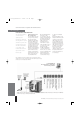
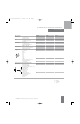
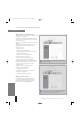
Graphic
2-3
This diagram illustrates how to wire the COM16 module if MODBUS is to
be used to switch the device open and closed. This diagram only applies
to 24V DC control voltage.
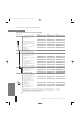
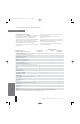
Graphic
2-4
Interposing relays are required if a control voltage different than 24V DC
is used. If the 1st shunt trip is not used to switch off the device, use
terminals X9.1 and X9.2 to utilize the 2nd shunt trip.
MODBUS Installation Guideline
The COM16 must be assembled and connected
as described in the WL Operating Instructions.
Of particular importance is the requirement to
ground the shield of the MODBUS cable.
WL UL 489_Com-section 2 1/28/05 1:09 PM Page 10