
User's Manual


Page 76 SITRANS LC 500 – INSTRUCTION MANUAL 7ML19985GE01
mmmmm
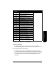
Appendix C
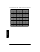
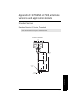
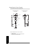
SITRANS LC 500 DD Menu/Variable Organization
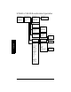
Device setup menu
PV digital value
PV upper range value
PV lower range value
SV digital value
SV upper range value
SV lower ran
g
e value
Process variables menu
Diagnostics/service
Basic setup menu
Detailed setup menu
Autocal
Review menu
Sensor digital value
Input percent range
A0 analog value
PV maximum recorded
PV minimum recorded
Reset max/min records
Self tes
t
Loop test
Calibration
Dac trim
Tag
PV digital units
Device info menu
PV transfer function
PV dam
p
in
g
value
Device type
Private label distribution
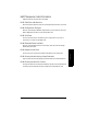
PV digital units
Sensor units
Upper sensor limit
Lower sensor limit
Minimum span
Damping value
Input percent range
Transfer function
Input range units
Upper range value
Lower range value
A0 analog value
A0 alarm code
Write protect
Manufacturer ID
Device ID
Tag
Descriptor
Message
Date
Universal revision
Transmitter revision
Software revision
Polling address
Request preambles
High calibration level
Low calibration level
Applied rerange
Keypad rerange
Zero correction
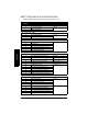
Measuring elements menu
Signal conditioning menu
Output conditioning menu
Device info menu
PV upper sensor limi
t
PV lower sensor limit
PV minimum span
PV sensor units
PV Upper range value
PV Lower range value
Damping value
Upper range value
Lower range value
Transfer function
Percent range
Analog output menu
Hart output menu
Private label distribution
Device type
Device ID
Tag
Date
Write Protect
Descriptor
Message
PV sensor serial number
Final assembly number
Device revisions menu
PV analog value
PV alarm select
Dac trim
Loop test
Polling address
Request preambles
Universal revision
Transmitter revision
Software revision
Root Menu
Device Setup Menu
Process Variables
Diagnostics/service
Basic Setup Menu
Detailed Setup Menu
Autocal Menu
Review Menu Device Info Menu
Output Condition Menu
Signal Conditioning Menu
Measuring Elements
Auto Calibration Menu
Analog Output
Hart Output Menu
Device Revisions