
Installation Instructions
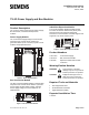

Document No. 553-142
Installation Instructions
June 4, 2010
Siemens Industry, Inc. Page 3 of 4
Installation
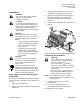
3.
Using a flat blade screwdriver, push in each
mounting tab until it clips onto the DIN rail.
WARNING:
Turn OFF AC power at the ON/OFF
switch in the Service Box or
transformer enclosure.
CAUTION:
UL Listings require NEC Class I and
Class II wiring be kept separate from
each other. Use separate conduit and
cable tie bars to separate Class I
Digital Output (DO) wires from all other
Class II wiring.
CAUTION:
The TX-I/O™ island bus must extend
from the male bus connector of the TX-
I/O Power Supply or Bus Connection
Module.
The TX-I/O Power Supply and Bus
Connection Module only supply 24
Vac to I/O modules on the male
bus connector.
I/O modules on the female bus
connector of the TX-I/O Power
Supply or Bus Connection Module
do not receive power and have a
fault condition.
CAUTION:
Only insert or remove the field panel
controller, TX-I/O Power Supply, and
Bus Connection Module when the
power is OFF.
This device includes electrical and
electronic components and must not be
disposed of as domestic waste. Product
recovery and disposal must comply with
all national and local regulations.
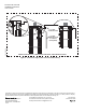
4.
Align an I/O module with the Power Supply or
Bus Connection Module, and slide the I/O
module down over the TX-I/O island bus
connector.
5. Push in each mounting tab until it clips onto the
DIN rail.
TXIO0064R1
1
2
3
5
4
Figure 3. Connecting Devices to the TX-I/O Island Bus.
Completing the Installation
CAUTION:
For RS-485 ALN or FLN, terminate
only one end of the shield wire on the
enclosure earth ground.
For a 3-wire system,
terminal is
connected to reference wire. Protective
ground terminal may be connected to
earth ground.
For a 2-wire system,
terminal is not
connected. Protective ground terminal
must be connected to earth ground.
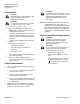
Basic Steps for Connecting Devices to
the DIN Rail
NOTE
: Do not connect the power or network
communication cable until instructed to do
so during start-up.
The island bus establishes its own connection when
TX-I/O™ devi
ces are plugged into one another on a
DIN rail.
1.
Terminate power wiring to the 24 Vac
removable plug.
1.
Slide out the mounting tabs.
2.
If necessary, terminate wires to the
communications terminals (CS and CD).
2.
Align the channel on the back of the device with
the DIN rail.
The install
ation is now complete.