
Installation Instructions

Document No. 553-142
Installation Instructions
June 4, 2010
2
13579111315
(1)
(1)
(2) (3) (4) (5) (6) (7) (8)
4
(2)
6
(3)
5
(4)
10
(5)
12
(6)
14
(7)
16
(8)
2
13579111315
(1)
(1)
(2) (3) (4) (5) (6) (7) (8)
4
(2)
6
(3)
5
(4)
10
(5)
12
(6)
14
(7)
16
(8)
1
2
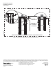
CS CD
24V
T
CS CD
BCM
24V24V
CS CD
24V
T
CS CD
2
13579111315
(1)
(1)
(2) (3) (4) (5) (6) (7) (8)
4
(2)
6
(3)
5
(4)
10
(5)
12
(6)
14
(7)
16
(8)
2
1357911
(1)
(1)
(2) (3) (4) (5)
4
(2)
6
(3)
5
(4)
10
(5)
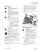
PS
PXC0009WDR1
3-WIRE
COMMUNICATION
TO COMPACT
(IF REQUIRED)
2-WIRE
COMMUNICATION
2-WIRE POWER
WIRING DIAGRAM IF ALL COMPONENTS ARE INSIDE THE SAME ENCLOSURE.
24V~ CS CD
24V~
Figure 5. TX-I/O Power Supply to Bus Connection Module Wiring.
Information in this document is based on specifications believed correct at the time of publication. The right is reserved to make changes as
design improvements are introduced. APOGEE and Insight® are registered trademarks of Siemens Industry, Inc. Other product or company
names mentioned herein may be the trademarks of their respective owners. © 2010 Siemens Industry, Inc.
Siemens Industry, Inc.
Building Technologies Division
1000 Deerfield Parkway
Buffalo Grove, IL 60089-4513
U.S.A
Your feedback is important to us. If you have
comments about this document, please send them
to SBT_technical.editor.us.sbt@siemens.com.
Document No.
Printed in the USA
Page 4 of 4