
Data Sheet for Product


16
Siemens
N4211en
Smart Infrastructure
2021-12-13
4
2
1
1
M
0
2
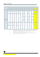
DN
=
Nominal size
H
=
Total height of actuator plus minimum mounting distance to wall or ceiling, for mounting,
connection, operation, maintenance, etc.
H1
=
Dimension from the pipe to the center to install actuator (upper edge)
Type
DN
B
C
C1
D
Rp
L1
L2
H1
H2
[mm]
[inch]
[mm]
VBI61.15..
15
26
34
48.5
1)
42
Rp ½
33,5
67
24.2
33.7
VBI61.15-6.3
34
49.5
1)
42
27.6
37.6
VBI61.20..
20
31
36.7
52
42
Rp ¾
36
72
27.6
37.6
VBI61.25..
25
39
44.8
64.5
42
Rp 1
42.5
85
30.5
40.5
VBI61.32..
32
48
52.6
76.5
42
Rp 1¼
49.5
99
34.3
44.3
VBI61.40..
40
55
57.1
84.5
42
Rp 1½
55
110
39.8
49.8
VBI61.50..
50
67
68.9
102.5
42
Rp 2
65.5
131
52.8
62.8
1)
Ball valve body extends above threaded connection
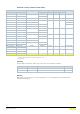
Typ
H
Weight
GQD..9A, GSD161.9A, GDB..9E..,
GDD161.9E
GMA..9E.., GLD161.9E..,
GLB..9E..
[mm]
[kg]
VBI61.15..
> 300
> 300
0,29
VBI61.15-6.3
0,305
VBI61.20..
0,375
VBI61.25..
> 320
> 320
0,605
VBI61.32..
-
0,95
VBI61.40..
-
1,365
VBI61.50..
-
> 335
2,215