
Data Sheet for Product

5
N4211en
Smart Infrastructure
2021-12-13
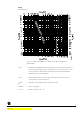
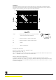
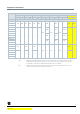
Cavitation
Cavitation increases wear and tear of the ball and seat and results in unwanted noise.
Cavitation can be prevented by not exceeding the differential pressures as per the flow
diagram and maintaining the static pressures depicted below.
0 100 200 300 400 500 600 700 800 900 10001100 12001300
25
20
15
10
5
0
2500
2000
1500
1000
500
0
1
4
0
°
C
1
8
0
°
C
1
6
0
°
C
1
2
0
°
C
1
0
0
°
C
8
0
°
C
Δp
max
=
Differential pressure at a nearly closed ball
valve to largely avoid cavitation
p
1
=
Static pressure at the ball valve inlet
P
3
=
Static pressure at the ball valve outlet
M
Pump
J
Water temperature
Example with hot water:
Pressure p
1
at ball valve inlet: 500 kPa (5 bar)
Water temperature: 120 °C
The above diagram clearly indicates that the maximum permissible differential pressure is
Δp
max
→ 200 kPa (2 bar) at a nearly closed ball valve.
Note on chilled water applications
To prevent cavitation in chilled water circuits, sufficient counter pressure must be
supplied to the ball valve outlet, e.g. using an additional butterfly valve downstream of the
ball valve. Maximum permissible differential pressure over the ball valve: See 80 °C curve
in the above diagram.