
Datenblatt


16
Siemens
N4212de
Smart Infrastructure
2021-12-13
4
2
1
2
M
0
2
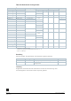
DN
=
Nennweite
H
=
Gesamthöhe des Stellgerätes plus Mindestabstand zur Wand oder Decke
für Montage, Anschluss, Bedienung, Wartung usw.
H1
=
Auflagemass ab Rohrleitungsmitte für den Aufbau des Stellantriebes
(Oberkante)
Typ
DN
B
C
C1
D
G
L1
L2
H1
H2
mm
Zoll
mm
VBG61.15..
15
27
43,5
59,5
42
G 1 B
43,5
87
24,2
33,7
VBG61.15-6.3
27
44,1
61
42
G 1 B
44,3
88,6
27,6
37,6
VBG61.20..
20
34
44,7
66
42
G 1 ¼ B
44,7
89,4
27,6
37,6
VBG61.25..
25
35
49,5
73
42
G 1 ½ B
49,2
98,4
30,5
40,5
VBG61.32..
32
38
63,7
94
42
G 2 B
57
114
34,3
44,3
VBG61.40..
40
49
74,3
107
42
G 2 ¼ B
63,8
127,6
39,8
49,8
VBG61.50..
50
61
82,1
123
42
G 2 ¾ B
69
138
52,8
62,8
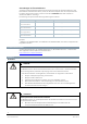
Typ
H
Gewicht
GQD..9A, GSD161.9A, GDB..9E..,
GDD161.9E
GMA..9E.., GLD161.9E..,
GLB..9E..
mm
kg
VBG61.15..
> 300
> 300
0,41
VBG61.15-6.3
0,45
VBG61.20..
0,52
VBG61.25..
> 320
> 320
0,75
VBG61.32..
-
1,2
VBG61.40..
-
1,84
VBG61.50..
-
> 335
2,83