Installation and Operations Manual Siemens VersiCharge™ 1 © 2014 Siemens Industry, Inc.
Contact Information Siemens Industry, Inc. Infrastructure & Cities Sector Low and Medium Voltage 5400 Triangle Parkway Norcross, GA 30092 1-800-241-4453 www.usa.siemens.com/versicharge info.us@siemens.com FCC Compliance This equipment has been tested and found to comply with the limits for a Class B digital device, pursuant to part 15 of the FCC Rules. These limits are designed to provide reasonable protection against harmful interference in a residential installation.
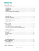
Table of Contents 1 Important Safety Information ....................................................................................................5 1.1 Read this First ...................................................................................................................5 1.2 Symbol Legend..................................................................................................................5 1.3 Product Labels.........................................................................
© 2014 Siemens Industry, Inc.
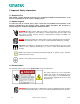
1 Important Safety Information 1.1 Read this First This manual contains important instructions for use during installation and maintenance of the Siemens VersiCharge™ electric vehicle charging station. 1.2 Symbol Legend To reduce the risk of electrical shock, and to ensure the safe installation and operation of the Siemens VersiCharge™, the following safety symbols appear throughout this document to indicate dangerous conditions and important safety instructions. DANGER Hazardous voltage.
Indicates connection point for Ground conductor. 1.4 Definitions The term EV used in this manual refers to an electric vehicle. The term AC used in this manual refers to alternating current. The term Universal unit refers to any VersiCharge with a plug and chord assembly attached, i.e. part numbers VC30XXXU**** (Indoor / Outdoor Use) The term Hardwired unit refers to any VersiCharge which is factory configured for hardwired installation only, i.e.
- - - - - - Failure to follow these instructions may lead to death, serious injury or property damage. Any electrical wiring required to install this device shall conform to applicable codes and standards (ANSI/NFPA 70). A qualified electrician is recommended to perform these tasks. To reduce the risk of electric shock, never service, install or uninstall this device from service while energized. This equipment has arcing or sparking parts that should not be exposed to flammable vapors.
interference will not occur in a particular installation. If this equipment does cause harmful interference to radio or television reception, which can be determined by turning the equipment off and on, the user is encouraged to try to correct the interference by one or more of the following measures: o Reorient or relocate the receiving antenna. o Increase the separation between the equipment and receiver.
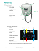
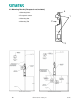
7 5 2: Device Layout 2.1 Exterior – Front 1 1. Pause Button 2. Delay Timer Button 3. Connector 2 4. Connector Holster 5. Halo Indicator 4 6. Closure Screws 6 7. Hinges 3 2.2 Exterior – LED Indicators 1. Pause 3 1 2 7 8 4 5 6 10 9 2. Charging 3. Power Available 4. Ready 5. Fault 6. Remote Control Activated 7. Service Portal 8. Time Delay 9. Hour Delay 10. Remote Control Lock Note: Wi-fi and zigbee communication are not enabled for these versions. 9 © 2014 Siemens Industry, Inc.
2.3 Mounting Bracket (Receptacle not Included) 4 1. Mounting Holes 2. Receptacle cutout 1 3. Mounting Slot 2 4. Mounting Tab 3 10 © 2014 Siemens Industry, Inc.
2.4 Exterior – Rear 1. Mounting Tabs 2. Fed from behind wiring option 3. Fed from the bottom wiring option 4. EV Cord 2 1 3 4 11 © 2014 Siemens Industry, Inc.
2.5 Interior – Connection Area 1. Line Conductor Connections 2. Ground Connection 3. Remote Control Interface 3 1 2 12 © 2014 Siemens Industry, Inc.
2.6 Device States EVSE's do not have the capability to determine whether your car has been charged or not, refer to car manual for indication of car battery status.
Section 3: Installation 3.1 Building Survey • Available voltage, current and frequency: § VersiCharge EV charging stations can draw up to 30A at 240 VAC, 50/60 Hz (7.2kW of power). The complete electrical structure of the building must be adequately sized to handle the entire building energy load, under peak conditions, as well as the charging station load under operation.
§ The VersiCharge will mount on the surface of the wall, protruding at least 15 inches, and a location for installation should be chosen where there is sufficient space to park an EV, walk past the device, open nearby doors, etc., without obstruction. § If the installation location is not already wired for installation, installation of the VersiCharge unit should be planned with an electrician and then the electrician should bring in the electricity according to those guidelines.
§ Receptacle will be located below VersiCharge mounting bracket, either to the left or the right of the stud to which the mounting bracket will be attached. Verify receptacle location complies with local code requirements. o NEC® 2011 specifies: Indoor (NEC® Article 625.29B) = installation 18 – 48 inches above ground level. o Verify local code with respect to installation height. 16 § Wire a standard NEMA 6-50 receptacle using appropriate wire.
Rear-fed, Cord-and-Plug Installation Mounting NOTE: Flush mount installations only, meaning the receptacle is even with wall in which it is installed. § Locate a stud within the wall to attach the mounting bracket. o For concrete or masonry walls, install appropriate anchors. o Verify that the stud or anchor and surrounding materials can handle the 20+ lbs load of the VersiCharge. § Ensure that receptacle can be flush mount installed to the left side of the mounting bracket.
§ To hang the unit onto the mounting bracket, place bottom mounting tab into corresponding slot in mounting bracket. Plug cord into receptacle. Rotate the unit towards the wall so that the hook on the unit goes over the top mounting bracket. § Secure VersiCharge to wall and mounting bracket 3.
o Disconnect the attachment plug wires from the terminal block by loosening screws in position 1, 2, and 3. o Do not adjust the two screws on top of the terminal block unit. These are for factory use only.
§ Using 7/16 inch socket head and drill, attach the Mounting Bracket to the wall using the two lag screws, ensuring that the cutout lines up with the conduit and that the two lag screws are going into the stud. § Route conduit to the opening of the unit and terminate appropriately.
o Settings 5-9 are for factory use only. These settings will result in a fault if used. § Verify that the VersiCharge is disconnected from power when changing the amperage adjustment dial Setting Label Current (A) Power (kW) 0 MIN 6 1.44 1 25% 7.5 1.8 2 50% 15 3.6 3 75% 22.5 5.4. 4 MAX 30 7.2 Circuit Requirements § Circuit must be sized for the max ampere requirement. Do not de-rate breakers or conductors based on amperage adjustment 3.
§ Control Switch input is a dry contact input from an external source. § Status Output indicates the charging status of the VersiCharge. § The Remote Control Interface is located inside the unit so to connect a device, the unit has to be opened by taking the following steps: § § Open hinged cover by loosening four cover Phillips closure screws. § Remove barrier by removing the two securing screws.
Section 4: Operation 4.1 Overview The VersiCharge EV Charging Stations incorporate industry accepted operating standards for EV charging. These include the operation and communication protocols between the VersiCharge and the EV, as well as the required safety features. This section explains in detail the steps of operation. 4.2 Typical Operation The VersiCharge is primarily a ‘plug-and-play’ device. § Descriptions of various device states can be found in Section 2.
The VersiCharge will automatically disconnect power in the event of a fault. § If a fault occurs during charging, the VersiCharge will disconnect power from the EV, with an audible click, and change to the ‘Fault’ state. The VersiCharge will automatically self-recover when all faults clear, with the exception of grounding faults. § For grounding faults, after 15 minutes, the VersiCharge will attempt to continue charging, and if no faults are present, will return to the ‘Charging’ state.
§ While in use, the cord can be unwrapped, loop by loop, to allow sufficient length of cord to be unwound to reach the EV receiver WARNING! Failure to properly protect the connector and the cord could result in damaged components, which could prevent the VersiCharge from functioning properly or create a hazardous situation. 4.5 Delay Timer The VersiCharge has a built in delay timer to allow users to select the time that they would like for their EV to charge.
State Name Description Halo Status Indicator Power Available 240V or 208V Power Present Off Ready to Charge EV detected, waiting for charging command from EV Green - Solid Charging Charging EV Green - Fading in and out Pause Operation paused Off Delay Timer Operation awaiting delay timer Off Remote System is controlled via remote control interface Off Halo Deactvation The Halo indicator on the versiCharge can be deactivated to marginally lower power consumption of your device during nor
§ When the external contact is closed, the alternate input will control the VersiCharge, preventing it from entering the ‘Charging’ state § The status output is a switch that indicates charging status. When the contacts are closed, the unit is in charging state © 2014 Siemens Industry, Inc.
Section 5: Troubleshooting 5.1 General Settings Some of the errors that occur are not caused by the VersiCharge, but by the EV compatibility or by settings which are turned on in the EV itself. § If the unit is going into fault, please check the settings in the EV to ensure that these are not causing the VersiCharge to stop charging. Many EVs have a setting for time of charge for example in which the user defines a preference of charging only in certain hours of the day/night.
Section 6: Warranty Limited Warranty Siemens Industry Inc. ("Siemens") has developed a highly reliable EV Supply Equipment (EVSE), branded as VersiCharge (“VersiCharge EVSE”), that is designed to withstand normal operating conditions when used in compliance with the Siemens Installation and Operations Manual supplied with system as originally shipped by Siemens.
product from Siemens, via a non-expedited freight carrier selected by Siemens, to locations within the United States (including Alaska and Hawaii) and Canada, but not to other locations outside the United States or Canada. The Limited Warranty does not cover shipping damage or damage resulting from mishandling by the freight carrier. Any such damage is the responsibility of the freight carrier.
exclusion(s) may not apply. This Limited Warranty gives the customer specific legal rights. The customer may have other rights that vary from state to state or province to province. 31 © 2014 Siemens Industry, Inc.
Section 7: Wiring Diagrams 32 © 2014 Siemens Industry, Inc.
© 2014 Siemens Industry, Inc.