Installation and Operations Manual Siemens VersiCharge SG™ 1 © 2015 Siemens Industry, Inc.
Contact Information Siemens Industry, Inc. Energy Management Division Low Voltage and Products 5400 Triangle Parkway Norcross, GA 30092 1-800-241-4453 www.usa.siemens.com/versicharge info.us@siemens.com FCC Compliance This equipment has been tested and found to comply with the limits for a Class B digital device, pursuant to part 15 of the FCC Rules. These limits are designed to provide reasonable protection against harmful interference in a residential installation.
Table of Contents 1 Important Safety Information ................................................................................................... 5 1.1 Read this First .................................................................................................................. 5 1.2 Symbol Legend................................................................................................................. 5 1.3 Product Labels.........................................................................
Section 6: Warranty ..................................................................................................................38 Section 7: Wiring Diagrams .......................................................................................................41 4 © 2015 Siemens Industry, Inc.
1 Important Safety Information 1.1 Read this First This manual contains important instructions for use during installation, operation and maintenance of the Siemens VersiCharge™ SG electric vehicle charging station. 1.2 Symbol Legend To reduce the risk of electrical shock, and to ensure the safe installation and operation of the Siemens VersiCharge™ SG, the following safety symbols appear throughout this document to indicate dangerous conditions and important safety instructions. DANGER Hazardous voltage.
Indicates connection point for Ground conductor. 1.4 Definitions The term EV used in this manual refers to an electric vehicle. The term AC used in this manual refers to alternating current. The term ‘VersiCharge SG’ unit refers to any Wi-Fi enabled VersiCharge SmartGrid unit with a plug and cord assembly attached, i.e. part number VCSG30GRYUW (Indoor / Outdoor Use).
1.6 Instructions Pertaining to a Risk of Fire or Electric Shock WARNING! When using electric products, basic precautions should always be followed, including the following. This manual contains important instructions for the Universal Unit that shall be followed during installation, operation and maintenance of the unit: - Read all of the instructions before using this product. - Failure to follow these instructions may lead to death, serious injury or property damage.
- This equipment has been tested and found to comply with the limits for a Class B digital device, pursuant to part 15 of the FCC Rules. Personal Protection Equipment: Use of proper personal protection equipment, including, but not limited to, eye protection, shock protection, gloves and other appropriate protection, is recommended when installing or servicing any electrical equipment DANGER Explosion hazard. This equipment has arcing or sparking parts that should not be exposed to flammable vapors.
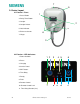
7 5 2: Device Layout 2.1 Exterior – Front 1 1. Pause Button 2. Delay Timer Button 3. Coupler 2 4. Coupler Holster 5. Halo Indicator 4 6. Enclosure Screws 6 7. Hinges 3 2.2 Exterior – LED Indicators 1. Power Available 1 2 3 4 5 6 7 8 9 10 11 2. Pause 3. Charging 4. Service Portal 5. Wi-Fi Status 6. Time Delay 7. Ready 8. Fault 9. Remote Control 10. Remote Control Lock 11. Time Delay Duration (hrs.) 9 © 2015 Siemens Industry, Inc.
2.3 Mounting Bracket (Receptacle not Included) 4 1. Mounting Holes 2. Receptacle cutout 1 3. Mounting Slot 2 4. Mounting Tab 3 10 © 2015 Siemens Industry, Inc.
2.4 Exterior – Rear 1. Mounting Tabs 2. Plug and cord assembly in fed from behind wiring option 3. Fed from the bottom wiring option 4. Coupler and cord assembly 2 1 3 4 11 © 2015 Siemens Industry, Inc.
2.5 Interior – Connection Area 1. Line Conductor Connections 2. Ground Connection 3. Remote Control Interface 4. Wi-Fi Module and CEA2045 Connector 4 1 3 2 12 © 2015 Siemens Industry, Inc.
2.6 Device States EVSE's do not have the capability to determine whether your car has been charged or not. Refer to car manual for indication of car battery status.
Section 3: Installation 3.1 Building Survey Available voltage, current and frequency: VersiCharge EV charging stations can draw up to 30A at 240 VAC, 50/60 Hz (7.2kW of power). The complete electrical structure of the building must be adequately sized to handle the entire building energy load, under peak conditions, as well as the charging station load under operation.
DANGER Explosion hazard. This equipment has arcing or sparking parts that should not be exposed to flammable vapors. This equipment should be installed at least 18 inches above floor or ground level. Use extreme caution and follow instructions carefully. 3.3 Cord-and-plug installation The standard VersiCharge SG unit arrives factory-configured for rear fed and bottom fed cord-and-plug installations. For hardwired installations, please refer to section 3.4 of this manual.
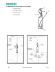
Hang the VersiCharge on the Mounting Bracket by first hooking the bottom of the unit into the mounting slot and then hooking the top into the mounting tab. Secure VersiCharge to wall and mounting bracket using provided screws. Ensure that the breaker for the circuit on which the receptacle is wired is turned to the ‘OFF’ position, plug the VersiCharge into the receptacle and switch the breaker to the ‘ON’ position.
Using 7/16 inch socket head and drill, attach the Mounting Bracket to the wall using two lag screws provided. Verify that lag screws are going into the stud. Before starting the step to hang the VersiCharge unit onto the mounting bracket, ensure that the circuit breaker on the circuit for the receptacle is turned to the ‘OFF’ position. To hang the unit onto the mounting bracket, place bottom mounting tab into corresponding slot in mounting bracket. Plug cord into receptacle.
Route conductors, with proper strain relief, into the VersiCharge from the conductor opening o Pull 3-6 inches of slack through the conductor opening Place bottom mounting tab into corresponding slot in mounting bracket. Secure VersiCharge to wall and mounting bracket Wire conductors (copper only) into device (L1, L2 and Ground) from connected conduit. Using torque screw driver, torque all lugs to 14.5 lb-in. Replace barrier and secure with the two screws which were removed in the beginning.
Setting Label Current (A) Power (kW) 0 MIN 6 1.44 1 25% 7.5 1.8 2 50% 15 3.6 3 75% 22.5 5.4. 4 MAX 30 7.2 Circuit Requirements Circuit must be sized for the max ampere requirement. Do not de-rate breakers or conductors based on amperage adjustment 3.6 Remote Control Interface The Siemens VersiCharge has a Remote Control Interface that allows charging to be controlled by an external device.
o Open hinged cover by loosening four cover Phillips closure screws. o Remove barrier by removing the two securing screws. o Remove connector to run wire o Route control wiring, with proper protection and strain relief, through the low voltage wire opening.
Select “Register” Complete the three registration steps displayed below: Key considerations while completing the registration process include: o Step 1 of 3: You must select the grey check mark to indicate you have read the terms and conditions of use. The check mark will turn blue when selected. Full terms and conditions may also be found at: www.usa.siemens.
The “power available” LED indicator will turn green and the “Wi-Fi Status” LED indicator will go through the following process: o Indicator should initially slowly blink red and then switch to slowly blink yellow o Once the indicator slowly blinks green, the charger has transitioned to access point (AP) mode and is ready to be connected to a Wi-Fi network Once in AP mode you may use your web enabled device (suggested laptop) to navigate to the following webpage: commission.versichargesg.
o Enter a “Charger nickname” of your choosing. Make sure to provide unique names if you have multiple chargers linked to your account (user name and password) o Enter the “Home wireless network SSID”. This entry is case sensitive. Make special note to select the 2.
o 24 For the cloud app you will use the navigation bar to select “Settings” then “Current EV Charger” to verify the connection © 2015 Siemens Industry, Inc.
Section 4: Operation 4.1 Overview The VersiCharge EV Charging Stations incorporate industry accepted operating standards for EV charging. These include the operation and communication protocols between the VersiCharge and the EV, as well as the required safety features. This section explains in detail the steps of operation. 4.2 Typical Operation The VersiCharge is primarily a ‘plug-and-play’ device. Descriptions of various device states can be found in Section 2.
For grounding faults, after 15 minutes, the VersiCharge will attempt to continue charging, and if no faults are present, will return to the ‘Charging’ state. During this 15 minute delay, the ‘Fault’ indicator on the unit will blink, the ‘2 Hour Delay’ indicator is illuminated, and the Halo on the unit will blink red simultaneously.
From either the ‘Charging’ state or the ‘Ready to Charge’ state, press the ‘Delay Timer’ button o Pressing the button once, will delay charging to 2 hours o Pressing the button twice, will delay charging to 4 hours o Pressing the button three times, will delay charging to 6 hours o Pressing the button four times, will delay charging to 8 hours o Pressing the button a fifth time will deactivate the timer and return the VersiCharge to the ‘ready to Charge’ state, and if the EV requires a charge, to the ‘Ch
Halo Deactivation The Halo indicator on the VersiCharge can be deactivated to marginally lower power consumption of your device during normal operation. This will prevent the Halo from illuminating in all states, except the ‘Fault’ state.
29 By clicking on the navigation symbol in the landing screen highlighted in the right hand screen above, you can see the overall structure of the application Menu Option Menu Option Description Charger Status Displays whether the charger has power available, is delayed, is connected to an EV, has experienced a fault, or is charging My account Enables you to view and edit the user information you entered when setting up the app, as well as unregister My charger “My charger” enables you to limit
Charger status This tab serves as the primary user interface for remote control of the VersiCharge SG, with the buttons on the left and right hand side of the screen having identical functionality as those on the face of the charger (seen below) The status screen displays the state in which the charger is operating. Shown above in the center is the delay state which can be remotely entered by pushing the delay button once. In this example the ‘charge’ state has been delayed by 2 hours.
My charger This tab allows you to control the power level as a percentage of maximum charge rate (30A). To adjust this rate, use the + and – buttons that are provided on the tab and then hit the refresh button shown in the graphic. This setting will take into account any adjustment of the amperage adjustment dial you may have made outlined in section 3.5.
Schedule The scheduling function allows you to automate your charging process based on your preferences. Use the scheduling function to select charge times for weekdays and weekends, with options for charge cycles both during the day and evening Power level may also be set to an adjusted rate for a scheduled charging session.
schedules based on times that work best for you. At the top right of every page, see cumulative energy consumption in kWh for the displayed period of time. Alerts The alerts tab allows you to select the charger events that would prompt an email to be sent to the address you entered during registration Please refer to the usa.siemens.
The cloud application has the same functionality as the phone app. The only differences between the two applications are structural in nature. The application landing screen is shown below and a table showing the equivalent phone or tablet page being listed for each tab located at the bottom of the web app page is provided.
Local Web Pages An alternative to cloud or smartphone applications for managing your VersiCharge SG is using the local web pages embedded in the charger. These web pages may be accessed by entering the individual IP address associated with a charger. This IP address may be found using a number of different apps; Fing Network Scanner is the recommended tool. Once the IP address is known, you may enter it in the search window of your browser of choice, connecting you to the local web pages for the charger.
The only differences between the two interfaces is additional event logging and troubleshooting dashboards. Accessing the local web pages allows you to operate your charger off of the Siemens cloud network, by doing this you cannot opt-in to utility demand response events. Additionally, by operating off the network, you can no longer access the charger using either the cloud or phone applications. 36 © 2015 Siemens Industry, Inc.
Section 5: Troubleshooting 5.1 General Settings Some of the errors that occur are not caused by the VersiCharge, but by the EV compatibility or by settings which are turned on in the EV itself. If the unit is going into fault, please check the settings in the EV to ensure that these are not causing the VersiCharge to stop charging. Many EVs have a setting for time of charge for example in which the user defines a preference of charging only in certain hours of the day/night.
Section 6: Warranty Limited Warranty Siemens Industry Inc., Energy Management Division, Low Voltage Products ("Siemens") has developed a highly reliable EV Supply Equipment (EVSE), branded as VersiCharge (“VersiCharge EVSE”), that is designed to withstand normal operating conditions when used in compliance with the Siemens Installation and Operations Manual supplied with system as originally shipped by Siemens.
The Limited Warranty covers both parts and labor necessary to repair the Defective Product, but does not include labor costs related to un-installing the Defective Product or re-installing the repaired or replacement product.
BE GIVEN FULL FORCE AND EFFECT WHETHER OR NOT ANY OR ALL SUCH REMEDIES SHALL BE DEEMED TO HAVE FAILED OF THEIR ESSENTIAL PURPOSE. THESE LIMITATIONS OF LIABILITY ARE EFFECTIVE EVEN IF SIEMENS HAS BEEN ADVISED BY THE CUSTOMER OF THE POSSIBILITY OF SUCH DAMAGES. This Limited Warranty gives the customer specific legal rights, which are customer’s exclusive remedies hereunder. The customer may have other rights that vary from state to state or province to province. province to province.
Section 7: Wiring Diagrams 41 © 2015 Siemens Industry, Inc.