
User Manual

Siemens Building Technologies VISONIK DCS Functions and System Messages VVS18 CM2U8567E / 04.1999
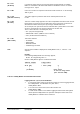
Landis & Staefa Division Function DPP 2-105
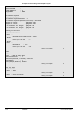
Channel(Data Processing)
----------------------------
Chan.No.=. : 1
Address=$d100'040 : $100'041
# Address Flag PAR TYP INT ORG from upto
------------------------------------------------------------------
$d100'041 INST I05m CIRC 19.07.1996 56 Hour
$d100'041 RDO 10:00
2 $d100'041 INST I60m CIRC 21.06.1996 28 Day
$d100'041 RDO 12:00
Entry=1 : >>o.k.!
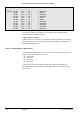
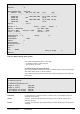
Chan.No. = 1. Format = Even Symbol =
Address = $d100'041 Par.Name = RDO
Log Type = INST Interval = I05m Buffer = CIRC
Colour = Black Pattern = 0 =
(................)
Multiplication = 1 Offset = 0
Format=Even :
Colour=Black : CYAN
Symbol= : +
Dot Pattern=0 :
Multiplication=1 :
Offset=0 :
Text :
Text : KUCHE
Entry in Graph 1
Chan.No.=. :
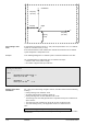
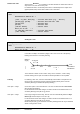
2.12.7.2 AXES, Change Axes System
Axes system definition takes place in two steps:
•
Co-ordinate system in paper units [mm].
•
Axes scaling in user units.
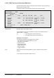
Co-ordinate System in Paper Units [mm].
First of all, the position and dimension of the co-ordinate system is entered using paper
units, which always refers to a printer terminal.
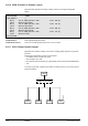
The co-ordinate system position is defined by its origin (meeting point of horizontal and
vertical axes).
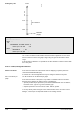
Co-ordinate System
------------------
Co-ordinate System=Slct'ble:
Length of X-Axis [mm]=150:
Length of Y-Axis [mm]=100:
X Co-ordinate for Origin [mm]=35:
Y Co-ordinate for Origin [mm]=25:
For A4 printers the maximum size of the x-axis is 150 mm. For VISONIK Insight, the
maximum size is 240 mm.
If "Choice" is specified the dimensions and origin of the co-ordinate system can be
defined by the user.
If "Default" is specified the above default values are automatically taken for dimensions
and origin.
Restriction
Choice
Default