
User Manual

CM2U8567E / 04.1999 VISONIK DCS Functions and System Messages VVS18 Siemens Building Technologies
2-202 Function PG Landis & Staefa Division
$PS'mm'
p
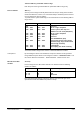
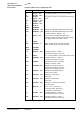
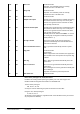
A DCS process image supports a maximum of 8 points per module of a BPS, PRV1 or
EKL.
The actual maximum possible number of points per module depends on the PS type
and also the respective module type.
Point type EKL PRV1 BPS
ML
MW
SB1
SBR1
SBR2
SBR3
STP
ST3P
STU
ZW
Digital inputs
Analogue inputs
Digital outputs
Digital o/p with FB
Digital o/p with FB
Digital o/p with FB
Analogue outputs
Analogue outputs
Analogue outputs
Counter inputs
0 . . 7
0 . . 3
0 . . 3
0 . . 1
---
0
0 . . 1
0 . . 5
0 . . 5
0 . . 1
0 . . 7
0 . . 3
0 . . 3
0 . . 1
---
0
0 . . 5
0 . . 3
0 . . 5
0 . . 1
0 . . 7
0 . . 7
0 . . 7
0 . . 3
0 . . 1
0 . . 1
0 . . 3
0 . . 3
0 . . 7
0 . . 3
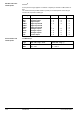
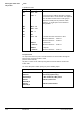
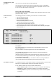
$PS'
Mmmm'Pp:
Type Mod. addr. range mmm Point addr. range p
PRV
BPS
001 . . 080
001 . . 112
1 . . max. 4
1 . . max. 4
EKL Bus and P-Bus
module points
P-Bus modules and
module points