
User Manual

Siemens Building Technologies VISONIK DCS Functions and System Messages VVS18 CM2U8567E / 04.1999
Landis & Staefa Division Function PG 2-205
Point type
Most data points must be generated using the function PG as described here. There
are, however, certain exceptions.
The following table is sorted by point types. It shows whether and how each point type
can be generated.
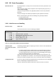
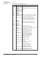
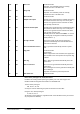
Pnt type CTYP Text Notes on generation
ML 0 Status input
Generate with PG.
MW 1 Measurement input
Generate with PG.
ZW 2 Counter value
Generate with PG.
SB1 3 Switch command 1-step
Generate with PG.
SBR1 4 Switch command 1-step
with feedback
Generate with PG.
SBR2 5 Switch command 2-step
with feedback
Generate with PG.
SBR3 6 Switch command 3-step
with feedback
Generate with PG.
STP 7 Position command
(pneumatic module)
Generate with PG.
STU 8 Position command
Generate with PG.
(voltage/current o/p)
ST3P 9 Position command
Generate with PG.
(3-point output)
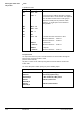
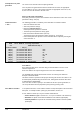
DI 12 Digital Input
Generate with PG.
AI 13 Analogue Input
Generate with PG.
CI 14 Counter Input
Generate with PG.
DO 15 Digital Output
Generate with PG.
AO 16 Analogue Output
Generate with PG.
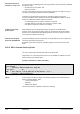
BLN 22 Building Level Network
When a PS is generated, the corresponding point
types are also generated automatically in the PS
–
BLN: communication between PS <--> DCS, and
–
OS: COLBAS supervision
.
OS 23 Operating System
When a PS is generated, the corresponding point
types are also generated automatically in the PS
–
BLN: communication between PS <--> DCS, and
–
OS: COLBAS supervision.
PS 24 Building Process Station
The process image of a PS is generated automatically
by the VISONIK DCS as soon as:
–
the PS is detected on the ring, or
–
a point is generated in the PS.
At the same time the corresponding point types are
also generated automatically in the PS
–
BLN: communication between
–
PS <--> DCS, and
–
OS: COLBAS supervision.
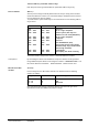
RGB 25 Regulator block
Generate with PG.
CVP 26 Conversion parameter set
Generate with PG.