
User Manual

CM2U8567E / 04.1999 VISONIK DCS Functions and System Messages VVS18 Siemens Building Technologies
2-208 Function PG Landis & Staefa Division
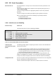
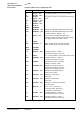
The correct CTYP must be entered at point generation.
If the I/O point to be generated is located on the EKL Bus or P-Bus, the appropriate
CTYP for ME, PS, ST, SC or CG must be selected. The appropriate CTYP for AI, AO,
DI, DO or CI must be entered in all other cases.
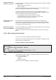
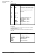
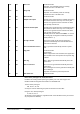
Notes on TEC room configuration
After point generation, up to 10 TEC controllers can be allocated to a TEC room via the
parameters TEC(1)..TEC(10).
The following procedure is mandatory for the allocation of controller numbers:
•
Select the desired TEC room.
•
Select the parameter TEC(1).
•
Enter the
control character '>'
.
Indexed parameter operation is activated.
•
The DCS opens the parameter TEC(1) again.
•
Enter the desired controller number (33..126).
The DCS then opens the parameter TEC(2), TEC(3) etc. successively.
•
Non-indexed parameter operation can be reactivated when required by entering the
control character
'<'
.
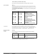
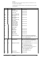
T8 10:25:43 Function=PNT : $100'TCR1
... ROOM TE'C1'ROOM"01 Training Department
-1°C ASPH/ASPC=20/26þ°C
Parameter=SOPST : TEC(1)
TEC(1) | Allocated TEC Units =34:
TEC(2) | Allocated TEC Units =36:
TEC(3) | Allocated TEC Units =0:
TEC(4) | Allocated TEC Units =0: 35
TEC(4) | Allocated TEC Units =35
TEC(5) | Allocated TEC Units =0:
TEC(6) | Allocated TEC Units =0:
ALconf | Configured as Alarm Point =0=No : No
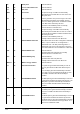
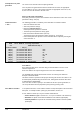
User address
Every data point that can be accessed using a technical address can have a user
address assigned to it.
Each user address can only be assigned once in the same VISONIK DCS.
The VISONIK DCS prompts with the basic structure for entering user addresses.
Example: "A00'A1'22"AAAA".
This basic structure is specified at the project start using the function 'SYS,ADR'. It can
be subsequently modified using the function UAX, although this should be done ONLY
IF ABSOLUTELY NECESSARY.
If the user does not wish to specify a user address at the time of point generation, he
can accept the basic structure proposed by the system by pressing <CR>.
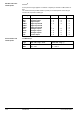
In an optimum structure, a User Address contains a unique description of the associated
data point - for example location, plant type, plant number, function, etc.
A User Address is made up of any user-related combinations of
–
Active characters
(digits 0-9, letters A-Z, a-z; up to a maximum of 26 characters).
–
Delimiters
for optical and structural subdivision of the address (apostrophe).
–
A dummy delimiter
to separate the redundant dummy address extension (double
apostrophe).
Consequences for point
generation
Control characters
< and >
User Address structure