
User Manual

Siemens Building Technologies VISONIK DCS Functions and System Messages VVS18 CM2U8567E / 04.1999
Landis & Staefa Division Function RPT 2-275
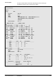
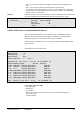
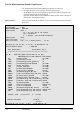
Explanation
Each entry in the maximum demand program register for the selected tariff group
(maximum demand point) is printed out on five lines in the report.
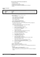
1st line
Each switch command point is displayed as follows:
•
Address and system text, possibly suffixed by a status indication. !MD indicates that
the corresponding RDO is determined by the maximum demand program.
•
Parameter RDO; resultant switching command
•
Parameter ERSTA (if <> .), e.g. ERSTA = OSV
•
Parameter OPMO; operation mode
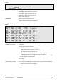
2nd line
All loads that are subject to the same tariff are combined in a tariff group. Each tariff or
meter group represents a single energy measurement location (maximum demand
point) that is completely independent of other tariff groups.
•
Marker:
!MD
indicates that the maximum demand program has changed this switch command
from its threshold value to its shed value.
Up to 100 separate switching priorities can be assigned within each tariff or meter
group.
The maximum demand program switches:
•
loads with low priority (low number) OFF first and ON last.
•
loads with high priority (higher number) OFF last and ON first.
•
loads of equal priority according to the "round-robin" procedure, i.e. the switch
command that has remained unchanged by the maximum demand program for the
longest time is changed first.
(set by the system!)
The system value is the value of the switch command in the maximum demand register
which is set by the DCS via TRR, DRR, PRR, manual intervention etc. (NOT maximum
demand program). The system value cannot be changed by the maximum demand
program nor can it be directly manipulated. However, it informs the MD program of the
state that the switch command (DO) should be in if the parameter RDO (resultant switch
command) is not modified by the MD program.
Out of the total available load in this MD register entry, the indicated switched load has
been reduced by the MD program; see also Parameters PN1 to PN3
.
The power than
can be switched ON and OFF for each switch value is defined by these parameters.
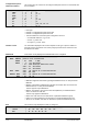
3rd line
All DO entries can be blocked for switching operations of the MD program at any time
using a flag. A blocking flag must have a "$ address" ($FLn) assigned to it.
•
Marker:
?FL
indicates that this MD entry is blocked by a flag.
Elapsed time in [Sec] or [Min] since the resultant switch command RDO of the DO point
last changed as a result of this MD program entry.
It can be seen from this indication:
•
how long it will take until the minimum or maximum threshold time and shed time
elapse, or
•
which of several entries with the same priority will be switched next.
When an MD program is first started (e.g. when the value of the parameter TGRP is set
from 0 to 1 in the MD point) these counters are started from zero.
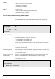
Status indication
TGRP
Priority
System value
Demand / Load
Blocking flag
Time