
User Manual


Siemens Building Technologies VISONIK DCS Functions and System Messages VVS18 CM2U8567E / 04.1999
Landis & Staefa Division Function TRND 2-317
2.31.2.2 Explanation
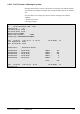
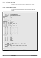
A user can define up to 16 Trendplot Sets. With parameter $Tn.TSET the required 'Set'
is output to the recorder. Sets can be freely exchanged whilst a recorder is active.
Up to 10 channels can be defined per Trendplot Set.
At this point, VISONIK prompts for an address.
Any point address in the system can be declared as a "Trend point".
This prompt is answered by entering either a User (UA) or Technical Address (TA).
The system can plot either analogue or digital points.
The required parameter's short name is entered.
These are left and right margin values which define the plot's scale.
Both positive or negative numbers for either margin may be entered to give the required
scale range.
The plot is then limited to the values set for left and right margins.
The left margin's scale value must be less than that of the right margin!
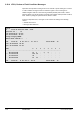
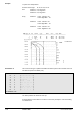
Valve position range 0...100%
Desired Trend range 25...35%
Plot 25% at left margin, 35% at right margin.
Entry Value - Left Mar = 25
Value - Right Mar = 35
9370Z26E
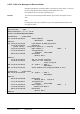
Step range of a switch Steps OFF, 1, 2, 3.
Desired Trend range Steps OFF,1,2,3.
Plot Step OFF to be at mid-scale.
Each step = 0,5 cm.
Entry Value - Left Mar = -10
Value - Right Mar = 10
9370Z27E
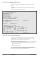
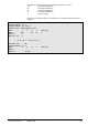
Set=1: 2
Trend Channel=1 : 1
Address= $1'04'01:
E01'L2'11
Parameter =SC : ME
Value - Left Mar=-20: 15
Value- Right Mar= 50: 30
Example
Example