4 315 ACVATIX™ PICVs PN 16 with flanged connections VPF43.. Pressure Independent Combi Valves · · · · · · With integrated pressure differential controller Valve body made of gray cast iron GJL-250 or GJL-400 DN 50 - 200 Volumetric flow 15 to 280 m3/h nominal, with presetting Equipped with pressure test points P/T Can be equipped with SAX..P.., SAV..P.. or SQV..P.. electromotoric actuators Use · For use in heating, ventilating and air conditioning systems, district heating, as a control valve.
Type summary Standard flow rate Product number Stock number DN VPF43.50F16 1) S55266-V100 50 VPF43.65F24 1) S55266-V102 65 1) S55266-V104 80 S55266-V106 - 100 VPF43.80F35 VPF43. 100F70 1) H100 & V min & V 100 ∆pmin [mm] 3 [m /h] 3 [m /h] [kPa] 2.3 15 4.4 25 5.3 34 12.1 68 18.5 110 25.6 148 95 210 4.3 25 6 35 20 See 40 High flow rate VPF43. 125F110 S55266-V108 125 VPF43. 150F160 S55266-V110 150 VPF43. 200F210 S55266-V148 200 VPF43.
Equipment combinations Actuators Valves SAX..P.. DN Standard VPF43.50F16 50 flow rate VPF43.65F24 65 VPF43.80F35 80 VPF43. 100F70 100 VPF43. 125F110 125 VPF43. 150F160 150 VPF43. 200F210 200 High flow VPF43.50F25 50 rate VPF43.65F35 65 VPF43.80F45 80 VPF43. 100F90 100 VPF43. 125 125F135 VPF43.
Technical / mechanical design 1 1 Ring with dial for presetting 2 Aperture for the differential pressure controller is linked with outlet port B 3 Differential pressure controller 4 Plug with variable presetting opening 5 Control valve 6 Pressure test point (P/T) at outlet port B, blue ribbon, P- 7 Pressure test point (P/T) at inlet port A, red ribbon, P+ A Inlet port A B Outlet port B 2 3 7 6 4 5 B 4315Z01 A Functional principle The PICVs VPF43..
Medium flow The medium entering the PICV (inlet port A) first passes through the control valve (5) with a linear characteristic and a stroke of 20 mm (DN 50…80) respectively 40 mm (DN 100…150). The actuator (not shown here) opens and accurately positions the control valve. Then, the medium flows through the variable presetting opening (4) which is connected to the ring with dial (1) for presetting the desired maximum volumetric flow.
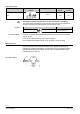
Sizing Basis of design 1. Determine heat demand Q [kW] 2. Determine temperature spread ΔT [K] 3. Calculate volumetric flow Engineering example & = Q [kW ] × 1000 é l ù V 1. 163 × DT [K ] êë h úû 4. Select suitable PICV VPF43.. 5. Determine dial setting using volumetric flow/dial presetting tables, see below. Example 1. Heat demand Q = 150 kW 2. Temperature spread ∆T = 6 K 3. Volumetric flow & = 150 kW × 1000 = 21'654 l / h = 21.6m 3 / h V 1.
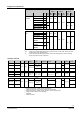
35 m3/h nominal VPF43.80F35 v̇ [m /h] 10.9 12.2 13.5 14.8 16.2 17.6 19.1 20.7 22.4 24.3 26.4 28.7 31.2 34 Dial Min. 0.2 0.4 0.6 0.8 1 1.2 1.4 1.6 1.8 2 2.2 2.4 2.6 2.8 3 3.2 3.4 3.6 Δpmin [kPa] 16.0 16.0 16.0 16.4 16.8 17.2 17.6 18.0 18.4 18.7 19.1 19.6 20.0 20.8 21.7 22.7 3.8 23.8 4 25 3 5.3 6.9 8.3 9.6 70 m3/h nominal VPF43.100F70 v̇ [m3/h] 12.1 15 18 21 23 25 28 30 32 35 38 40 43 47 51 56 Dial Min. 0.2 0.4 0.6 0.8 1 1.2 1.4 1.6 1.8 2 2.2 2.4 2.6 2.8 3 3.2 3.4 3.
Engineering notes Valve Symbols / Direction of flow Flow in control mode VPF43.. variable PICV Valve stem retracts extends closes opens The direction of flow indicated (arrow on the valve body) is mandatory! The valves should preferably be mounted in the return pipe where temperatures are lower and where the sealing gland is less affected by strain. Symbol Symbol used in catalogs and application descriptions Symbol used in diagrams There are no standard symbols for PICVs in diagrams.
Installation notes Presetting It is recommended to mount the actuator before the presetting is made. 1. Mount actuator and fix valve neck coupling 2. Mount valve stem coupling and tighten slightly 3. Make presetting according to table under "Volumetric flow/dial presetting" on page 6. Do NOT adjust presetting to a dial reading lower than “0.6”. 4. Tighten stem coupling 8 mm Using an open-end wrench and turn the stem with dial to the desired presetting position.
Commissioning notes The valves must be commissioned with the actuator correctly fitted. Strong pressure impacts can damage closed PICVs. The PICVs have to be open when flushing or pressure testing the system. Strong pressure impacts can damage closed PICVs. Differential pressure Δpmax across the valve’s control path is not allowed to exceed 600 kPa. Manual control Only possible with mounted actuator. Maintenance notes The VPF43.. PICVs are maintenance-free.
Technical data Functional data PN class PN 16 as per EN 1333 Permissible operating pressure 1600 kPa (16 bar) as per ISO 7628 / EN 1333 Volumetric flow deviation < ±10% within differential pressure range Valve characteristic Linear as per VDI/VDE 2173 Leakage rate Class IV (0…0.
Dimensions / weight Dimensions Refer to "Dimensions" on page 12 Flange connections To ISO 7005-2 Pressure test points (P/T-ports) G ¼ inch (connection) 2 mm x 40 mm (measuring tips) Weight Refer to "Dimensions" on page 12 General ambient conditions Operation EN 60721-3-3 Class 3K5 0…55 °C 5...95 % r.h. Environmental conditions Temperature Humidity Transport EN 60721-3-2 Class 2K3 -30...65 °C < 95 % r.h. Storage EN 60721-3-1 Class 1K3 -15...50 °C 5...95 % r.h.
Revision Numbers Product number Valid from rev. no. Product number Valid from rev. no. VPF43.50F16 ..A VPF43.50F25 ..A VPF43.65F24 ..A VPF43.65F35 ..A VPF43.80F35 ..A VPF43.80F45 ..A VPF43.100F70 ..A VPF43.100F90 ..A VPF43.125F110 ..A VPF43.125F135 ..A VPF43.150F160 ..A VPF43.150F200 ..A VPF43.200F210 ..A VPF43.200F280 ..
Documentation form Installed location Valve type Actuator Type Valve Size Planned Presetting Required ∆pmin (kPa) Verified ∆p (kPa) Flow1 (l/h) 1) Flow = if Verified ∆pmin > Required ∆pmin, then Flow is as per presetting in datasheet, otherwise check. Issued by Siemens Switzerland Ltd Smart Infrastructure Global Headquarters Theilerstrasse 1a 6300 Zug Switzerland Tel. +41 58-724 24 24 www.siemens.