
Data Sheet for Product

9 / 17
Siemens Combi valves, PN 25 CE1N4855en
Smart Infrastructure 2020-10-19
Engineering notes
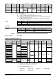
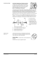
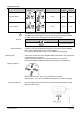
Valve Symbols / Direction of flow Flow in control mode Valve stem
VP..46.. VP..46..Q retracts extends
Combi valve VPP46.. variable closes opens
Combi valve VPI46.. variable closes opens
The direction of flow indicated (arrow on the valve body) is mandatory!
The valves should preferably be mounted in the return pipe where temperatures
are lower and where the sealing gland is less affected by strain.
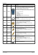
Symbol used in catalogs and application descriptions Symbol used in diagrams
There are no standard symbols
for Combi valves in diagrams.
A strainer or dirt trap should be fitted upstream of the valve to enhance reliability.
Remove dirt, welding beads etc. from valves and pipes.
Do not insulate the actuator bracket, as air circulation must be ensured!
Combi valve and actuator can be straightforwardly assembled on site. Special tools
or adjustments are not required.
Prior to mounting the actuator, the required volumetric flow must be set.
The valve is supplied complete with Mounting Instructions (74 319 0649 0 b).
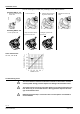
Thermal actuators STA.., STP.. may be installed in any position.
Actuators SSA.., SAY.. must be installed horizontally up to 90° and not hanging.
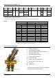
The AL60 supporting ring must be put into position before mounting the actuator
SUA21/3 onto the valve.
Symbols
Recommendation
Mounting notes
Mounting positions
AL60 supporting ring