
Data Sheet for Product


Siemens
Smart Infrastructure – Building Products
–8–
usa.siemens.com/fire
Fire Terminal Board (and equipment)
The Fire Terminal (Model FT2050)
consists of the Fire Terminal Board
(Model FTI2001-U1); that stores the
Standard Operating Unit (or the
Operating Unit with LEDs), and a one-
height-unit enclosure.
Each Model FT2050 terminal contains
one (1) backlit, 2” ─x─ 4-3/4” (5.1 cm.
─x─ 12.1 cm.) Video Graphics Array
(VGA) monochrome LCD screen with
LEDs for displaying system status. An
audible will sound when there are
‘unacknowledged’ events on the
system.
The display of each operating unit categorizes events by
type, providing a separate event tab for Alarm, Gas Alarm,
Supervisory, and Trouble events. The quantity of active
events of each type is listed in each event tab. The display
provides two (2) full lines of text message for each event.
Each event can have a 40-character custom message
describing the location for a given event. In addition to the
text message, the system displays the category of the active
event: (e.g. – Automatic Alarm, Water Flow, Manual, etc.)
– the category means more to responding officials than
models.
The Fire Terminal Boards contain the site-specific program
configuration which is created in the custom-configuration
tool, ‘Desigo Works’.
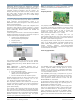
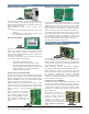
NAC Expansion Module
The NAC expansion module (Model FCI2011-U1) is an
optional module that is connected to the peripheral boards
(Models FCI2016-U1, FCI2017-U1), providing additional NACs
to 252-point and 504-point systems, respectively.
One (1) ‘Class A’ or two (2) ‘Class B’ NACs are provided with
the following Desigo systems:
▪ Model FV2025 (252-point)
▪ Model FV2050 (504-point)
Each NAC is rated at 3A. Each NAC expansion module is
monitored for open-line and short-circuit conditions.
When installed on a Model FV2025 or Model FV2050 Desigo
FACP, the releasing module contains an integral manual-
disconnect switch for releasing circuits. This essential
feature protects the releasing circuits from accidental
discharge during maintenance.
Activation can be accomplished via cross zoning of
automatic detectors or manual activation within one (1)
FACP. A pre-discharge countdown timer is available for
display at either the Standard Operating Interface Unit, or
Operating Interface Unit with LEDs.
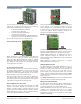
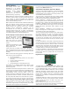
Remote Peripheral Module (with RS─485 interface)
The Remote Peripheral Module
(FCA2018-U1) provides a means of
connecting a Desigo panel to a
parallel printer for creating a hard
copy of system-status and
configuration reports. This
supervised, intelligent module
contains built-in transient
protection and plain-decimal
addressing.
Model FCA2018-U1 is remotely connected to the Model
FCA2016-U1 RS─485 communication bus from any Desigo
system enclosure. Model FCA2018-U1 uses ‘Class B’ (Style 4)
or ‘Class A’ (Style 6) wiring, and provides two (2) RS─232
(serial) ports and a single parallel port that allow connection
to the parallel printer (Model PAL-1).
When Model PAL-1 is used with the remote peripheral
module, Model FCA2018-U1 supervises the printer for On /
Off Line, Power On, Paper Out, Paper Jam, and wiring-fault
conditions, as required by UL for NFPA 72 proprietary
systems.
Event and report printing is generated either at the Standard
Operating Interface Unit, or Operating Interface Unit with
LEDs on the main Desigo system.
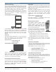
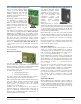
LED Option Module(s)
LED option modules provide LED annunciation of system
activity. For instance, Model FCM2023-U2 can either be
configured for up to 24 indicator zones, or for 48 individual
LEDs. Each zone for Model FCM2023-U2 contains one (1)
RED / GREEN bi-color LED and one (1) YELLOW LED.
Model FCM2034-U2 is the other version of the Desigo LED
option module. Used exclusively in Canadian applications,
Model FCM2034-U2 can also either be configured for up to
24 indicator zones, or for 48 individual LEDs. However, each
zone contains one (1) RED / YELLOW bi-color LED and one
(1) YELLOW LED.
Any event can be assigned to each LED, which may be
configured as a ‘static’ or ‘flashing’ indicator using the
Desigo custom-configurable software tool, ‘Desigo Works’.
Normally, the LED indicator is used as a zone indicator.
The LED option module is connected to the peripheral data
bus, and can be cascaded to up to a maximum of four (4)
LED modules. A space is provided for labeling of LED
functions. The label slides behind a clear, protective
membrane.
Blank Option Module
Model FCM2022-U2 is a blank-option module intended to
cover any blank LED areas where LED modules are not being
occupied. The Blank and LED Option Modules are mounted
on the inner door of a Desigo enclosure. Any combination of
modules may be mounted on the inner door. Up to four (4)
total modules can be supported.
Desigo Fire Components (cont.)
Model
FTI2001-U1
Model
FCA2018-U1
Model
FCI2011-U1