
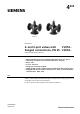
Data Sheet for Product


2 / 18
Siemens 2- and 3-port valves with flanged connections, PN 25 CE1N4405en
Smart Infrastructure 2019-05-24
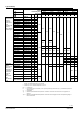
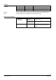
Type summary
Valves
Actuators
SAX..
3)
SKD..
2)
SKB..
SAV
3)
SKC..
Stroke
20 mm
40 mm
PN 25
PN 16
1)
Positioning force
800 N
1000 N
2800 N
1600 N
2800 N
Data sheet
N4501
N4561
N4664
N4503
N4566
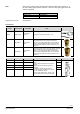
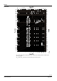
DN
k
vs
S
V
Δp
s
Δp
max
Δp
s
Δp
max
Δp
s
Δp
max
Δp
s
Δp
max
Δp
s
Δp
max
Stock no.
[m
3
/h]
[kPa]
Fluids
Preferred flow
direction
A-AB with
fluids for low
noise
operation and
high kvs-
values with all
actuator types
VVF53.15-0.16
S55208-V100
15
0.16
> 50
2500
1200
2500
1200
2500
1200
-
-
-
-
VVF53.15-0.2
S55208-V101
15
0.2
VVF53.15-0.25
S55208-V102
15
0.25
VVF53.15-0.32
S55208-V103
15
0.32
VVF53.15-0.4
S55208-V104
15
0.4
VVF53.15-0.5
S55208-V105
15
0.5
VVF53.15-0.63
S55208-V106
15
0.63
VVF53.15-0.8
S55208-V107
15
0.8
VVF53.15-1
S55208-V108
15
1
VVF53.15-1.25
S55208-V109
15
1.25
VVF53.15-1.6
S55208-V110
15
1.6
> 100
VVF53.15-2
S55208-V111
15
2
VVF53.15-2.5
S55208-V112
15
2.5
VVF53.15-3.2
S55208-V113
15
3.2
VVF53.15-4
S55208-V114
15
4
VVF53.20-6.3
S55208-V116
20
6.3
VVF53.25-5
S55208-V117
25
5
1600
2100
VVF53.25-6.3
S55208-V118
25
6.3
VVF53.25-8
S55208-V119
25
8
VVF53.25-10
S55208-V120
25
10
VVF53.32-16
S55208-V122
32
16
900
750
1200
1100
VVF53.40-12.5
S55208-V123
40
12.5
550
500
750
650
2000
1250
1150
VVF53.40-16
S55208-V124
40
16
VVF53.40-20
S55208-V125
40
20
VVF53.40-25
S55208-V126
40
25
VVF53.50-31.5
S55208-V127
50
31.5
350
300
450
400
1200
1150
750
700
VVF53.50-40
S55208-V128
50
40
VVF53.65-63
S55208-V129
65
63
-
-
-
-
-
-
450
400
700
650
VVF53.80-100
S55208-V130
80
100
250
225
450
400
VVF53.100-160
S55208-V131
100
160
160
125
300
250
VVF53.125-250
S55208-V132
125
250
125
90
175
160
VVF53.150-400
S55208-V133
150
400
80
60
125
100
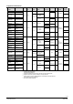
Fluids and
Steam
Compensated
valves are
optimized for
a single flow
direction for
fluids and
steam.
DN 50..150:
AB-A
DN 200/250:
A-AB
VVF53.50-40K
S55208-V134
50
40
> 100
-
-
2500
1250
2500
1250
-
-
-
-
VVF53.65-63K
S55208-V135
65
63
-
-
-
-
2500
1250
VVF53.80-100K
S55208-V136
80
100
VVF53.100-150K
S55208-V158
100
150
VVF53.125-220K
S55208-V159
125
220
VVF53.150-315K
S55208-V160
150
315
VVF53.200-450K
S55208-V161
200
450
> 50
1200
800
VVF53.250-630K
S55208-V162
250
630
1000
800
1)
DN 15…50: Flange dimensions for PN 16 and PN 25
DN 65…250: Flange dimensions only for PN 25
2)
Usable up to a max. medium temperature of 150 °C
3)
Usable up to a max. medium temperature of 130 °C
DN = Nominal size
k
vs
= Flow nominal value of cold water (5...30 °C) through the fully opened valve (H
100
) at a differential pressure of
100 kPa (1 bar)
S
v
= Rangeability
∆p
s
= Maximum permissible differential pressure at which the motorized valve still closes securely against the
pressure
∆p
max
= Maximum permissible differential pressure across the valve’s throughport for the entire positioning range of
the motorized valve