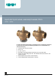
ACVATIX™ 2-port and 3-port valves, externally threaded, PN16 VVG44.., VXG44.. In small and medium-sized heating, ventilating and air conditioning systems as a control valve for mixing and diverting functions or as a shutoff valve. For closed circuits only. ● ● ● ● ● ● ● A6V10960349_en--_c 2021-02-23 Housing made of bronze CC499K DN 15...40 kvs 0.25...25 m3/h Flat sealing, externally threaded connections G..B, as per ISO 228-1 Siemens can deliver fitting sets ALG.. with threaded connection and ALS..
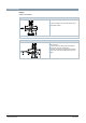
Technical design Design Valve cross-section: VVG44.. Guided parabolic plug, integrated in the valve stem. The seat is pressed to the valve body with the aid of special gland material. Caution: The 2-port seat valve does not become a three-port valve by removing the cover plate! VXG44.. Guided parabolic plug (as of DN25) which is integrated in the valve stem. The seat is fitted in the through-port and attached directly to the valve body in the bypass.
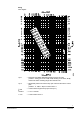
Sizing Flow diagram: Δpmax = Maximum permissible differential pressure across the valve (VXG44..: mixing port: Ports A-AB, B-AB, diverting: Ports AB-A, AB-B), valid for the entire actuating range valve-actuator unit Δpv100 = Differential pressure across the fully open valve and the valve’s control path (VXG44..: A - AB, B - AB) at a volume flow V100 100 Siemens Smart Infrastructure = Volume flow through the fully open valve (H100) 100 kPa = 1 bar ≈ 10 mWS 1 m3/h = 0.
Valve flow characteristic VVG44.. Valve flow characteristic: Through-port: 0…100% linear as per VDI / VDE 2173 VXG44.. Valve flow characteristic: Through-port: Linear as per VDI /VDE2173 Bypass: Linear as per VDI /VDE2173 Mixing: Flow from port A and B to port AB Diverting: Flow from port AB to port A and B Port A = Variable flow Port B = Bypass (variable flow) Port AB = Constant flow Use the three-port valve primarily as a mixing valve.
Cavitation Cavitation increases wear and tear on the parabolic plug and seat and results in unwanted noise. Cavitation can be prevented by not exceeding the differential pressures as per the flow diagram and maintaining the static pressures depicted below.
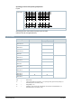
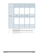
Operating pressure and operating temperature Liquids: Operating pressure [bar] Operating temperature [°C] Operating pressure and medium temperature per IS0 7005 (Observe all local and applicable laws). Type summary Type DN kvs Sv 3 [m /h] VVG44.15-0.25 15 0.25 >50 VXG44.15-0.25 VVG44.15-0.4 0.4 VXG44.15-0.4 VVG44.15-0.63 0.63 VXG44.15-0.63 VVG44.15-1 1 VXG44.15-1 VVG44.15-1.6 1.6 >100 VXG44.15-1.6 VVG44.15-2.5 2.5 VXG44.15-2.5 VVG44.15-4 4 VXG44.15-4 VVG44.20-6.3 20 6.
Accessories Fittings Type Stock number Description ALG..2 BPZ:ALG..2 ALG..2B S55846-Z1.. 2 piece fittings set for 2-port valves, existing of 2 cap nuts, 2 insert nuts, and 2 flat seals. ALG..3 BPZ:ALG..3 ALG..3B S55846-Z1.. ALS..2 BPZ:ALS.. ALG..2B are fittings made of brass for media temperatures up to 100 °C 3 piece fittings set for 3-port valves, existing of 3 cap nuts, 3 insert nuts, and 3 flat seals. ALG..
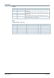
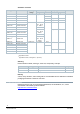
Equipment combinations Valves SAS.. actuators Dpmax Mixing VVG44.15-0.25 1) Dps Diverting [kPa] [kPa] 400 1600 1) VVG44.15-0.4 VVG44.15-0.63 VVG44.15-1 725 VVG44.15-1.6 VVG44.15-2.5 400 VVG44.15-4 VVG44.20-6.3 750 VVG44.25-10 400 VVG44.32-16 250 250 VVG44.40-25 125 125 VXG44.15-0.25 400 100 VXG44.15-0.4 VXG44.15-0.63 VXG44.15-1 VXG44.15-1.6 VXG44.15-2.5 VXG44.15-4 VXG44.20-6.3 VXG44.25-10 VXG44.32-16 250 50 VXG44.
Valves Fittings set Threaded connection Malleable cast iron Brass Welded connection 1) Steel Type / Item NO. Type Item NO. Type / Item NO. ALG152 ALG152B S55846-Z100 ALS202 VVG44.20-6.3 ALG202 ALG202B S55846-Z102 ALS252 VVG44.25-10 ALG252 ALG252B S55846-Z104 - VVG44.32-16 ALG322 ALG322B S55846-Z106 - VVG44.40-25 ALG402 ALG402B S55846-Z108 - VXG44.15-0.25 ALG153 ALG153B S55846-Z101 - VXG44.20-6.3 ALG203 ALG203B S55846-Z103 - VXG44.
Actuators: Overview Typ3 Stock number Operating voltage Signal Time 3-position 120 s SAS31.00 S55158-A106 SAS31.03 S55158-A107 30 s SAS31.50 S55158-A108 SAS31.53 S55158-A109 SAS61.03 1) S55158-A100 SAS61.03U 2) S55158-A100-A100 SAS61.03/MO S55158-A121 SAS61.
Notes Safety DANGER There is a risk to operating personnel and device when working on the unit Failure to comply with these safety notes can result in personal injury and damage to property from pipe pressure, electrical voltage, or device in operation. Note the following when servicing a valve/actuator: ● ● ● ● ● Switch off both pump and operating voltage. Close shutoff valves. Release pressure in the pipes and allow them to cool down completely.
Pipe connection Avoid leakage: ● Install fittings as per ISO 7-1. ● Do not use too much hemp or PTFE tape. ● Do not tighten pipe threading to "the very end". Flow direction Make sure that the valve is mounted in the proper flow direction. A symbol is applied to the valve body: VVG44.. : Flow direction: VXG44.. : Mixing Diverting A / B to AB: AB to A / B: Commissioning The actuator must be properly mounted or manually adjusted before commissioning the valve. VVG44..
Warranty Technical data on specific applications are valid only together with Siemens products listed under "Equipment combinations". Siemens rejects any and all warranties in the event that third-party products are used. Technical data Functional data VVG44.. VXG44.. PN class PN 16 per ISO 7268 Operating pressure Per ISO 7005 within the permissible media temperature as per Section Technical design [➙ 2] Characteristic curve 0…100 % linear as per VDI / VDE 2173 Leakage rate 0…0.
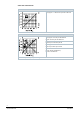
Dimensions VVG44.. VXG44.. 14 Siemens Smart Infrastructure DN = Nominal size H = Total height of actuator plus minimum mounting distance to wall or ceiling, for mounting, connection, operation, maintenance, etc.
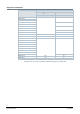
Valve type DN VVG44.15-0.25 15 B G L1 L2 L3 H1 H2 H Weight mm Inch mm mm mm mm mm SAS.. kg 8,5 G 1B 100 50 58 45 55 >381 0.65 49 59 0.67 53 63 0.77 VVG44.15-0.4 VVG44.15-0.63 VVG44.15-1 VVG44.15-1.6 VVG44.15-2.5 VVG44.15-4 12 VVG44.20-6.3 20 9 G 1¼B VVG44.25-10 25 11 G 1½B VVG44.32-16 32 VVG44.40-25 40 VXG44.15-0.25 15 105 52.5 G 2B 59 68 78 >396 1.0 62.5 71 81 >399 1.48 63.5 77.5 87.5 >406 1.95 G 2¼B 130 65 76 80.5 90.5 >409 2.
Type Article number For valve type G Rp ALS202 BPZ:ALS202 VVG44.15.. [inch] [inch] G1 26.8 ALS252 BPZ:ALS252 VVG44.20 G 1¼ 33.7 - - VVG44.25 - - - - VVG44.32 - - - - VVG44.40 - - Filter 4212M03 Type 1) DN b c G Inch 1) L H Kvs Weight mm mm mm mm ALX15 15 12 38 G½ 54 27 3.5 0.178 kg ALX20 20 15 43 G¾ 67 34 5.8 0.290 ALX25 25 16 53 G1 79 41 9.1 0.410 ALX32 31 17 64 G 1¼ 98 51 19 0.680 ALX40 40 18 70 G 1½ 106 57 24 0.