
User's Manual

Communication
PROFIBUS PA
Introduction
9/44
Siemens ST PCS 7 · November 2007
9
■
Design
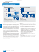
Basic PROFIBUS PA design versions when using the DP/PA link as the
router
Basic PROFIBUS PA design versions are presented at this point.
In these configuration examples, DP/PA links are used in each
case as the DP/PA router. Up to 5 DP/PA couplers can be oper-
ated in a DP/PA link. Mixed configurations (e.g. line and ring on
one link) are also possible. The DP/PA router can also be imple-
mented with a DP/PA coupler. In this case, the PROFIBUS DP
connection is directly on the coupler instead of per interface
module.
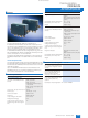
Linear architecture with single coupler
In this design version, each PROFIBUS PA line is linked with one
DP/PA coupler of a DP/PA router. Depending on the operating
environment, you can use either the FDC 157-0 DP/PA coupler
(up to Ex zone 2) or the Ex [i] DP/PA coupler (up to Ex zone 1).
The DP/PA router can be connected to a single or redundant
PROFIBUS DP.
Linear architecture with redundant couplers
The active field splitter (AFS) connects a PROFIBUS PA line with
two FDC 157-0 DP/PA couplers of a DP/PA router. This router is
operable on a single or redundant PROFIBUS DP. The AFS
switches the PROFIBUS PA line to the active one of the two re-
dundant couplers.
Flexible Modular Redundancy is possible at the device level by
grouping individual devices in different PROFIBUS PA lines.
Only one PROFIBUS PA line can be configured with coupler re-
dundancy on each DP/PA router. A PROFIBUS PA ring cannot
then be operated on this router.
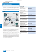
Ring architecture
Active field distributors (AFD) integrate PROFIBUS PA field
devices via 4 short-circuit proof spur line connections into
a PROFIBUS PA ring with automatic bus termination. The
PROFIBUS PA ring is connected to two FDC 157-0 DP/PA cou-
plers of a DP/PA router. The DP/PA router can be operated on a
single or redundant PROFIBUS DP. Up to 8 AFDs can be config-
ured per ring.
Flexible Modular Redundancy is possible at the device level by
grouping individual devices on different AFDs. Only one ring can
be configured on each DP/PA router. A PROFIBUS PA line with
coupler redundancy cannot then be operated on this router.
The following limits must be observed for a PROFIBUS PA ring
with respect to the configuration with PROFIBUS PA devices:
• Max. 31 PROFIBUS-PA devices
• Max. current consumption of all PROFIBUS-PA devices: 1 A
Particular advantages of the ring architecture:
• High availability
• Transparent redundancy management of the intelligent
FDC 157-0 DP/PA couplers for the higher-level system
• Active bus terminations for automatic bus termination in the
FDC 157-0 DP/PA couplers and the AFDs permit:
- Automatic, bumpless isolation of defective sub-segments in
event of short-circuit or wire breakage
- Changing of the ring configuration and the instrumentation
during operation, including addition or removal of ring seg-
ments
• Safety-related and fault-tolerant applications with low device
and cabling overheads
■
Technical specifications
PROFIBUS PA
PROFIBUS PA
PROFIBUS PA
PROFIBUS DP
Active field
splitter
Active field distributors
DP/PA Link
DP/PA Link
with redundant DP/PA couplers
DP/PA Link
with redundant DP/PA couplers
Direct fieldbus interfacing
AS 414FH/
AS 417FH
PROFIBUS PA
Data transmission
MBP
Transmission rate
31.25 Mbit/s
Cable
2-wire shielded
Type of protection
EEx(ia/ib)
Topol ogy
Line, tree, ring
PA devices per segment/coupler
31
PA devices per DP/PA link
64
Cable length per segment depen-
dent on transmission rate
1900 m: standard
1900 m: EEx(ib)
1000 m: EEx(ia)
© Siemens AG 2007