
User's Manual

Communication
PROFIBUS PA
Routers: DP/PA link and DP/PA coupler
9/47
Siemens ST PCS 7 · November 2007
9
■
Technical specifications
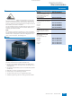
DP/PA coupler
Connection for PROFIBUS PA
• DP/PA coupler Ex [i] 2 terminals of a 4-pole screw-type
terminal, integral terminating
resistor
• DP/PA coupler FDC 157-0
4-pole screw-type terminal for
connection and looping through,
selectable terminating resistor
Connection for PROFIBUS DP
9-pin Sub-D plug,
contact assignment as described
in IEC 61158/EN 50170
Backplane bus
Connection through S7 back-
plane bus connector (only neces-
sary for DP/PA link); non-floating
The active BM DP/PA bus mod-
ules are required for the hot
swapping function
Diagnostic displays
• DP/PA coupler Ex [i] and
DP/PA coupler FDC 157-0
Bus activity "DP" (yellow)
Bus activity "PA" (yellow)
24 V DC "ON" (green)
• Additive with DP/PA coupler
FDC 157-0
Group fault "SF" (red)
Bus fault "BF" (rot)
DP/PA coupler activated, feed-
ing/transmitting "ACT" (yellow),
only with PA redundancy
Power supply
24 V DC (20.4 V ... 28.8 V)
Current consumption
• DP/PA coupler Ex [i] Max. 400 mA
• DP/PA coupler FDC 157-0
Max. 2300 mA
Voltage at coupler output
• DP/PA coupler Ex [i] 13 V ... 14 V DC
• DP/PA coupler FDC 157-0
31 ± 1V DC
Max. current at coupler output
• DP/PA coupler Ex [i] 110 mA
• DP/PA coupler FDC 157-0
1 A (up to 50 °C), 0.8 A (up to
60 °C)
Power loss
• DP/PA coupler Ex [i] Approx. 7 W
• DP/PA coupler FDC 157-0
Approx. 13.4 W
Operating temperature
• DP/PA coupler Ex [i] and
DP/PA coupler FDC 157-0
-25 ... +60 °C
(horizontal installation)
-25 ... +40 °C (vertical installation)
Dimensions (W x H x D) in mm
80 x 125 x 130
Weight
Approx. 515 g
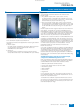
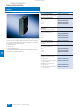
IM 153-2 High Feature (for extended temperature range)
Function
Linking of PROFIBUS DP
(9.6 kbit/s to 12 Mbit/s, slave
functionality) and PROFIBUS PA
with support of the "Configuration
in Run" function
The DP/PA link function is only
implemented by extending the
IM 153-2 High Feature with one or
more DP/PA couplers. Stand-
alone operation of the IM 153-2
High Feature is not possible.
1 Y coupler, up to
5 DP/PA couplers or up to
64 slaves can be connected
Isolation from the higher-level DP
master system
Interfaces
• Connection for PROFIBUS DP 9-pin Sub-D plug, contact assign-
ment as described in
IEC 61158/EN 50170, Vol. 2
• Backplane bus
Connection through S7 back-
plane bus connector, non-floating
Bus modules and profile rails for
hot swapping are required for the
hot swapping function and for a
redundant PROFIBUS DP inter-
face module.
Diagnostic displays
Group fault "SF" (red)
Bus fault DP "BF 1" (red)
Bus fault PA "BF 2" (red)
IM active "ACT" (yellow)
24 V DC "ON" (green)
Power supply
24 V DC
Current consumption
Max. 100 mA (in DP/PA link)
Max. 200 mA (in Y-link)
Power loss
Approx. 2 W (in DP/PA link)
Approx. 4 W (in Y-link)
Voltage failure bridging
20 ms
Mechanical design of power
supply
4-pin screw terminal, short-
circuiting link between PE and
M24; the short-circuiting link must
be removed for floating operation
(independent of this, the DP inter-
face is always floating)
Permissible operating temperature
-25 ... +60 °C
(horizontal installation)
-25 ... +40 °C (vertical installation)
Dimensions (W x H x D) in mm
40 x 125 x 130
Weight
Approx. 350 g
© Siemens AG 2007