
User Manual


CE1N5364E / 09.11.1998 Siemens Building Technologies
2/4 Landis & Staefa Division
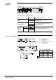
On the M-bus signal converter, the direction and type of the current data flow
are indicated by LEDs:
LED Designation Status Data flow
LED 1 (green) “ON” On Bus voltage present, master in idle state
Flashing Bus voltage present, master sending
LED 2 (yellow) “SLAVE” On Slave sending
Off Slave in idle state
LED 3 (yellow) “MAX” On Normal bus current exceeded
LED 4 (red) “SHORT” Flashing at 2 Hz Overcurrent
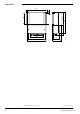
The M-bus signal converter consists of casing and detachable mounting base. The
casing is designed for wall mounting.
When closed, no indication or setting elements are visible. When opening the bottom
section of the casing, the connection terminals and LEDs can be accessed.
The terminal blocks carry two rows of contacts. The top row is used for the positive
potentials while the bottom row is used for the negative potentials.
The RS-232 interface card is an extra plug-in card. The card and its LEDs can be
accessed after removing the unit cover.
The local regulations on electrical installations must be complied with.
For the design of M-bus systems, please refer to the Planning Handbook, J5361.
Connect the DC 42 V power pack to the terminals 42 V + and - and to the earth terminal
E.
It must be made absolutely certain that the polarity of the power pack will be
correct!
Before making the connections, it is recommended to check the polarity with a
multimeter.
conformance to
EMC directive 89/336/EEC
Low voltage directive 73/23/EEC
Operating voltage
(safety extra low voltage to EN 60730) DC 42 V
Power consumption 25 VA
Degree of protection (when cover is closed) IP40 to EN 60 529
Safety class I to EN 60 730
Perm. ambient temperatures
Transport and storage – 25...+ 65 °C
Operation 0...55 °C
Weight 1.1 kg
Mechanical design
Engineering notes
Fitting notes
Technical data