
User Manual


3 / 8
Siemens Electronic connection for valves with magnetic actuator CA1N4591en
Building Technologies 2019-02-28
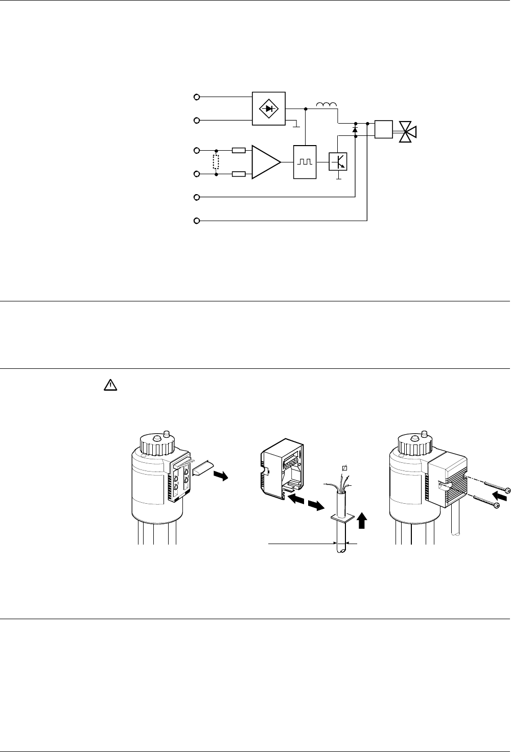
Technical design
The differential amplifier with signal inputs [3] and [4] is isolated from the AC supply
by a high resistance.
For 3-wire applications the signal negative [3] must be connected to AC supply
terminal [1].
1
2
3
4
5
6
–
–
+
50203 B
~
AC 24 V
~
+
DC 0 ... 10 V
(DC 4 ... 20 mA)
DC 0 ... 20 V Phs
T R
G
V
E
Q
M
–
+
E Electronic phase cut conditioning
G Bridge rectifier
M Valve with magnetic actuator
Q Phase cut output
T Input resistance < 150 Ω
(ZM120/A, 121/A, ZM220/A with DC 4...20 mA only)
V Differential amplifier
Sizing
The transformer is sized by applying the following formula:
Transformer power P
Tra
= 1.4 · Sum of the individual loads
Mounting notes
Always switch off the power supply before connecting or disconnecting the
electronic connection ZM.. or ZM../A terminal housing. Never remove or fit
electronic connections with switched on operating voltage!
9F676 A
9F677 A
B
ZM2... max ø 13.1 mm
A
C
ZM1... max ø 11.8 mm
max 4 mm
2
9F681A
It is important to use the cable cross-sections appropriate to the various cable
lengths used.
Maintenance notes
Electronic connections require no maintenance.
Transformer sizing
Caution!