
Manual and User Guide
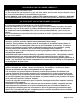
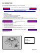
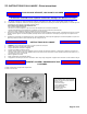
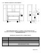
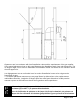
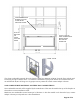
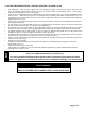
Table Of Contents
- TABLE 1
- Figure 1
- INSTALLATION CODES
- CODES D'INSTALLATION
- TO TURN GAS OFF TO APPLIANCE
- COMMENT COUPER L’ADMISSION DE GAZ
- L’APPAREIL
- The minimum vent system for horizontal termination must consist of:
- The maximum horizontal vent system consists of:
- The minimum vent system for horizontal termination must consist of:
- The maximum horizontal vent system consists of:
- The minimum vent system for horizontal termination must consist of:
- The maximum horizontal vent system consists of:
- The minimum vent system for horizontal termination must consist of:
- The maximum horizontal vent system consists of:
- The minimum vent system for horizontal termination must consist of:
- The maximum horizontal vent system consists of:
- The maximum vertical system consists of:
- Apply RTV high temperature
- sealant around male pipe.
- 3.3.9 PRIMARY AIR ADJUSTMENT / AJUSTEMENT DE L'AIR PRIMAIRE
- CORRECTIVE ACTION
- SYMPTOM
- 1. Weak or improperly located pilot flame
- 2. Defective thermocouple
- 3.Thermocouple not installed properly
- 4. Open wire connection in pilot circuit
- 5. Defective Valve
- 1. Loose or defective connections
- III. Main burner will not light
- 1. Valve control off
- 2. Blockage at the burner (line, orifice, or ports)
- 3. Defective remote
- 4. Defective wiring or connections
- 5. Defective Valve
- I. Soot deposits
- 1. Air inlet blocked or restricted
- 2. Vent system is restricted or inadequate
- 3. Logs are sooting up
- V. Flame burns blue and lifts off burner
- 1. Insufficient combustion air being supplied
- 2. Manifold pressure set too high
- 3. Vent system restricted
- VI. Main flame does not burn properly
- VII. Flames impinge on firebox top
- 1. Vent system is restricted or inadequate
- 2. Manifold pressure too high
- 8.0 LABEL INFORMATION
- WARNING
- Electrical Grounding Instructions
- APPENDIX A (AMERICAN FLAME VALVE INFORMATION)
- APPENDIX A (Continued)
- APPENDIX B (NG – LP CONVERSION KITS)

Page 17 of 54
Clearances are in accordance with local installation codes and the requirements of the gas supplier.
**The mantel placement chart on this page illustrates the allowable mantel sizes and placements. The
45 degree angle can be used to determine the allowable mantel size based on the elevation above
the units upper trim.
Les dégagements sont en conformité avec les codes d'installation locaux et les exigences du
fournisseur de gaz.
** Le tableau placement manteau sur cette page illustre les dimensions et les emplacements
admissibles cheminée. L'angle de 45 degrés peut être utilisé pour déterminer la taille permise
manteau repose sur l'élévation au-dessus de la garniture unités supérieures.
CAU TION
ATTENTION
When using paint or lacquer to finish the mantel, such paint or lacquer must be heat
resistant ( up to 250
o
F ) to prevent discolorations.
Lors de l'utilisation de peinture ou de laque à la fin de la cheminée, de peinture ou
laque doit être résistante à la chaleur (jusqu'à 250o F) pour prévenir la décoloration.
58.00