MODEL 5100-XX-IT IT Series TOXIC GAS SENSOR MODULE Version 2.0 APPLICABILITY & EFFECTIVITY Effective for all Model 5100-XX-IT and 5100-XX-IT-SS Modules manufactured after March 1, 2008 including.
THIS PAGE INTENTIONALLY LEFT BLANK Contents
TABLE OF CONTENTS 1. PRODUCT DESCRIPTION .............................................................................................................................1 1.1 GENERAL........................................................................................................................................................1 1.2 PRODUCT CONFIGURATION........................................................................................................................1 1.3 THEORY OF OPERATION ......
6.5 INSTALLATION INSPECTION ......................................................................................................................27 6.5.2 INSPECTION AND TROUBLESHOOTING GUIDE ...............................................................................28 6.5.3 IF MODULE DOES NOT RESPOND TO GAS ......................................................................................28 6.5.4 IF THE MODULE DISPLAYS “STARTING” FOR MORE THAN 1 HOUR .............................................
1. PRODUCT DESCRIPTION 1.1 GENERAL The Model 5100-XX-IT Toxics Gas Sensor Module is a member of the Information Technology ”IT” family of gas sensor transmitter modules.
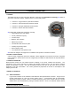
accessible from the cover plate as illustrated in Figure 3-1. Figure 3-6 in this manual provides the wiring terminations for connections to the Sentry controller. When the module is operated in conjunction with a Sentry controller, the alarms outputs in the module can both be set to “Sentry”, allowing the Sentry controller to manage alarm acknowledge and reset rather than the sensor module.
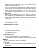
Figure 1-1 Model 5100-05-IT Toxic Gas Sensor Module – Aluminum Enclosures, Dimensions Figure 1-2 Model 5100-05-IT Toxic Gas Sensor Module – 316 Stainless Steel Enclosures, Dimensions .
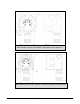
Figure 1-3 Model 5100-XX-IT Toxic Gas Sensor Module – Mounting Options 1.4.8 TRANSMITTER ELECTRONICS Electronic Assembly consist of one top transmitter board (connected to the cover plate) and on lower interface board. Connectors for wiring for power, signal interface and alarm relays are located on the interface board assembly 1.4.9 SENSOR ASSEMBLY The sensor assembly includes an explosion proof housing containing the gas sensor and a wiring harness for connection to the transmitter.
2. CAUTIONS & WARNINGS 2.1 INTRODUCTION Although IT Transmitter Modules are designed and constructed for installation and operation in industrial applications including "hostile" environments, caution should be taken to insure that the installation is made in compliance with this instruction manual and that certain procedures and conditions are avoided. This chapter discusses the necessary cautions. Read the entire chapter prior to installation of the equipment. 2.
THIS PAGE INTENTIONALLY LEFT BLANK Page: 6
3. INSTALLATION NOTE All IT modules are factory are pre-configured and calibrated. All modules are tagged to indicate the configuration including the sensor module number. Identify all components during unpacking and install using the factory configuration. 3.1 SENSOR MODULE LOCATIONS Select locations for each sensor modules based on the following: • Modules should be placed close to the potential source of gas. • Modules should be placed in areas accessible for calibration.
NOTES The drain wire of shielded cable must NOT be used as one of the conductors. Installation and wiring must be in accordance with the National Electrical Code. Temperature o rating of cable wire must be at least 75 C. If cable runs through higher temperature environments, it must be specified for that environment. 3.3 ENCLOSURE INSTALLATION To protect the transmitter and sensor assembly they should be removed from the enclosure and preserved until final installation and wiring termination.
6. Carefully return the transmitter to the enclosure installing it over the two stand-off’s. Tighten the retaining screws into the stand-offs.
3.5 MODULE ADDRESS SWITCH For digital interface applications the module address switch (or Modbus node) must be set per Table 3-2: POSITION ADDRESS POSITION ADDRESS 1 Sensor 1 9 Sensor 09 2 Sensor 2 A Sensor 10 3 Sensor 3 B Sensor 11 4 Sensor 4 C Sensor 12 5 Sensor 5 D Sensor 13 6 Sensor 6 E Sensor 14 7 Sensor 7 F Sensor 15 8 Sensor 8 0 Software Menu Table 3-2 Sensor Module Address Switch Positions NOTE For Sentry applications only sensor addresses 1-8 are allowed.
Figure 3-2 Interface Board Connectors Figure 3-3 RS-485: 120 ohm termination not selected, BIAS shunted for 100K ohm bias Page: 11
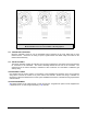
Figure 3-4 4-20mA Circuit Types Page: 12
Figure 3-5 4-20mA Circuit Type Connections for 5100-XX-IT Page: 13
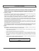
For end of line, refer to Figure 3-3 Figure 3-6 Wiring Connections for Modbus and Sentry Interface Page: 14
- OUT + SWITCH IN+ - IN - + + IN SWITCH 4-20 GND 4-20 P1 4.
THIS PAGE INTENTIONALLY LEFT BLANK Page: 16
4. OPERATION 4.1 INTRODUCTION – HUMAN-MACHINE INTERFACE SYSTEM The Gas Sensor Module utilizes a visual menu system operated by means of a magnet. A magnetic tool (5358-50) is supplied for this purpose. The menu system is used to configure alarm set-points, calibrate the sensor module, and for maintenance procedures and alarms acknowledge. 4.2 HUMAN-MACHINE INTERFACE The module menu system is operated by means of directing the magnet stick toward each of four independent hall-effect magnetic switches.
4.3 MAIN MENU Table 4-1 describes the primary man-machine interface operation. Key Function M S M S M S M S E T E T E T E T Display Description Mode Switch [M] Enter Switch [E] Up Switch [▲] Previous Menu Down Switch [▼] Next Menu 5100-XX First screen at power up: Model No. VXX-XX-- Second screen at power up: Version No.
Model 5100-XX-IT Toxic Gas Sensor Module 4.4 CONFIGURE SET-POINTS The sensor module set-points menu is used to initially set-up the alarm set points, relay actions, gas type and range, 4-20 mA action and RS-485/Sentry address and baud rates. • Alarm Set-points: Once the Set-up menu is selected, press [E] to activate the Alarm Set-point screen. Use the [▲] or [▼] keys to select Low Alarm or High Alarm menu. Key [▲] will adjust the setpoint upwards and Key [▼] will adjust the value downwards.
Model 5100-XX-IT Toxic Gas Sensor Module Key Function Display --0%LEL- M S M S M S M S M S M S M S M S E T E T E T E T E T E T E T E T Description Reference Default Display Mode ALMRSET: Mode Function - Alarm Reset Mode CALIB:-- Mode SETUP:--- Enter Alarms S.P. Function - Alarm Adjust * A Below Down Relays S.P. Function - Relays Adjust * B Below Down Gas S.P. Function - Range Adjust * Page 21 Down 4-20mA S.P. Function - 4-20 mA Adjust * Page 21 Down RS-485 S.P.
Model 5100-XX-IT Toxic Gas Sensor Module Gas Range Adjustment Example M E S T M E S T M S M S M E T E T E S T Enter Range Enter *100 PPM Down 10 PPM Down USER Enter 100 PPM S.P.
Model 5100-XX-IT Toxic Gas Sensor Module 4.5 MAINTENANCE FUNCTIONS The maintenance menu enables the operator to view sensor and software versions. Sierra Monitor technical support has access to other values as needed.. The maintenance menu operation is described in Table 4-4.
Model 5100-XX-IT Toxic Gas Sensor Module THIS PAGE INTENTIONALLY LEFT BLANK Page: 23
Model 5100-XX-IT Toxic Gas Sensor Module 5. CALIBRATION 5.1 CALIBRATION FREQUENCY The 5100-XX-IT has been calibrated in the factory prior to shipment. It is recommended that the user check calibration before placing in service. The toxic sensor module must be calibrated every six months. Periodic functional tests are advisable for critical applications and hostile environments.
Model 5100-XX-IT Toxic Gas Sensor Module 5.3.1 SENSOR EXPOSURE TO GAS Calibration gas must be delivered to the sensor using the flow rate and duration listed in below: Model 5100-03-IT 5100-04-IT 5100-05-IT 5100-06-IT Gas Oxygen Carbon Monoxide Hydrogen Sulfide Chlorine Key Function E T E T E T M E S T Mode ALMRSET: Mode CALIB:-- Enter Reference Default Display Mode Function - Alarm Reset Mode Function - Calibrate Operation: Confirm area clear of gas, or apply zero air to sensor.
Model 5100-XX-IT Toxic Gas Sensor Module 6. SERVICE 6.1 SENSOR MODULE CONFIGURATION The gas sensor module is comprised of the following sub-assemblies (Figure 6-1): 5100-XX-IT Gas Sensor Module SPL21810 Aluminum Enclosure (SPL32178 316SS Enclosure) SPL21825 Transmitter Assembly XXXXXXX Sensor Assembly (See Appendix B) 5200-XX-IT Sensor (See Appendix B) 6.
Model 5100-XX-IT Toxic Gas Sensor Module The enclosure should be replaced if the cover threads or conduit threads have been damaged, or if the enclosure has been damaged sufficiently that it no longer meets the required NEMA classification. To replace the enclosure follow the transmitter and sensor assembly removal instructions, remove the damaged enclosure from its conduit, install a new enclosure and replace the transmitter and sensor assembly. 6.
Model 5100-XX-IT Toxic Gas Sensor Module 6.5.1.2 SENSOR MODULE INSTALLATION • Module installation in conformance with this manual. • Modules accessible for calibration. • Wiring terminations clean and correct. 6.5.1.3 MOISTURE TRAPS AND RAINSHIELDS • Conduit seals and drains installed to avoid moisture build up in electronics enclosure.
Model 5100-XX-IT Toxic Gas Sensor Module 7. APPENDICES APPENDIX A - SPECIFICATIONS Sensor type: Max. Range User Settings Range Zero Drift Repeatability Linearity Resolution Response Time (1) Accuracy Sensor Life 5100-03-IT O2 0-25 %Vol +/- 0.1% +/- 0.2% +/- 0.2% +/- 0.1% <10 sec +/- 0.2% 2 years Electrochemical 5100-04-IT CO 0-1000 PPM 0-100, 0-500, variable +/- 1 PPM +/- 1 PPM +/- 1 PPM 0.5 PPM <25 sec. +/- 1 PPM 2 years 5100-05-IT H2S 0-100 PPM 0-10, variable +/- 0.5 PPM +/- 1 PPM +/- 1 PPM 0.
Model 5100-XX-IT Toxic Gas Sensor Module Modbus: Warranty: Baud: Parity: Stop bit: Data bits: 38400 (Adjustable 2400 to 38400 Baud) None 1 8 Flow Control: Memory map: None Appendix E Limited Warranty 2 years Specifications subject to change without notice Ordering Information: 5100 XX |- 5100 Series | |- 03 = O2 |- 04 = CO |- 05 = H2S |- 06 = Cl2 IT | | |- IT Series YY | | | |- Al (Aluminum Enclosure) |- SS (Stainless Steel) ZZ | | | |- 01= Sentry, RS-485, 4-20mA, & Digital Input |- 02= Sentry,
Model 5100-XX-IT Toxic Gas Sensor Module APPENDIX B: - MODEL NUMBERS & PARTS LIST Sensor Module 5100-03-IT 5100-03-IT-SS 5100-04-IT 5100-04-IT-SS 5100-05-IT 5100-05-IT-SS 5100-06-IT 5100-06-IT-SS Gas Sensor Module, Oxygen Gas Sensor Module, Oxygen, Stainless Steel Enclosure Gas Sensor Module, Carbon Monoxide Gas Sensor Module, Carbon Monoxide, Stainless Steel Enclosure Gas Sensor Module, Hydrogen Sulfide Gas Sensor Module, Hydrogen Sulfide, Stainless Steel Enclosure Gas Sensor Module, Chlorine Gas Sensor
Model 5100-XX-IT Toxic Gas Sensor Module APPENDIX C: LIMITED WARRANTY SIERRA MONITOR CORPORATION warrants its products to be free from defects in workmanship or material under normal use and service for two years after date of shipment. SMC will repair or replace without charge any equipment found to be defective during the warranty period. Final determination of the nature and responsibility for defective or damaged equipment will be made by SMC personnel.
Model 5100-XX-IT Toxic Gas Sensor Module APPENDIX D: REMOTE SENSOR/DISPLAY DRAWING 5394-52 Page: 33
Model 5100-XX-IT Toxic Gas Sensor Module APPENDIX E: MODBUS MEMORY MAP Read Register Table Register 40001 40002 40003 40004 40005 40006 40007 40008 40009 40010 40011 40012 40013 40014 40015 40016 40017 40018 40019 40020 40021 40022 40023 40024 40025 Description Concentration Temperature High Alarm Relay Low Alarm Relay Low Alarm Value High Alarm Value Reserved Reserved Reserved Reserved Trouble Bits Trouble High Alarm Immediate Low Alarm Immediate Random ID Restart Count Run time – high Run time – low Ma