MODEL 4501-XX 2-Wire Series TOXIC GAS SENSOR MODULE APPLICABILITY & EFFECTIVITY Effective for all Model 4501-XX Modules manufactured after September 1, 2006. 4501-04 FM Pending 4501-05 FM Approved 4501-06 FM Pending Instruction Manual Part Number T13022 Rev.
Model 4501-XX Toxic Gas Sensor Module FM PERFORMANCE APPROVAL ONLY THE FOLLOWING ITEMS, FUNCTIONS AND OPTIONS ARE FM* APPROVED Model 4501-05 Hydrogen Sulfide Gas Sensor Module Sensor Module Model 4501-05 Sensor Module - Hydrogen Sulfide Calibration Equipment Model 1250-01 Gas Sensor Calibration Kit, Type A Model 1260-05 Hydrogen Sulfide in N2, 25 ppm Gas Cylinder Model 1260-45 Hydrogen Sulfide in N2, 10 ppm Gas Cylinder Model 5358-01 Calibration Adapter Notes: 1) Apparatus must be installed in
Model 4501-XX Toxic Gas Sensor Module TABLE OF CONTENTS 1. PRODUCT DESCRIPTION .............................................................................................................................1 1.1 GENERAL........................................................................................................................................................1 1.2 MOUNTING CONFIGURATION.................................................................................................................
Model 4501-XX Toxic Gas Sensor Module 7.4.2 CABLING INSTALLATION .....................................................................................................................16 7.4.3 SENSOR MODULE INSTALLATION .....................................................................................................16 7.4.4 MOISTURE TRAPS AND RAINSHIELDS..............................................................................................17 7.4.5 STANDARD VOLTAGES .................................
Model 4501-XX Toxic Gas Sensor Module 1. PRODUCT DESCRIPTION 1.
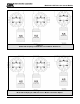
Model 4501-XX Toxic Gas Sensor Module 1.4 MECHANICAL The sensor module is comprised of the following three primary components: 1.4.1 ENCLOSURE Explosion proof, rain-tight stainless steel electrical housing with three ¾” FNPT conduit hubs. The enclosure cover has a viewing window. The 3 conduit hubs combined with the rotatable faceplate enable the user to mount the module in a variety of configurations. See Figure 1-2 for details. 1.4.
Model 4501-XX Toxic Gas Sensor Module Figure 1-1 Model 4501-05 Hydrogen Sulfide Gas Sensor Module– Dimensions Figure 1-2 Model 4501-05 Hydrogen Sulfide Gas Sensor Module– Orientation Options Page: 3
Model 4501-XX Toxic Gas Sensor Module 2. CAUTIONS & WARNINGS 2.1 INTRODUCTION Although the 4501-XX Gas Sensor Module is designed and constructed for installation and operation in industrial applications including hostile environments, caution should be taken to insure that the installation is made in compliance with this instruction manual and that certain procedures and conditions are avoided. This chapter discusses the necessary cautions. Read the entire chapter prior to installation of the equipment.
Model 4501-XX Toxic Gas Sensor Module 3. QUICK START 3.1 OVERVIEW The gas sensor module has been supplied factory calibrated and ready for immediate installation and operation. An installer familiar with installation and operation of gas detection products can use this section to begin immediate use of the module. 3.2 WIRING Provide two conductor shielded wiring from the power supply/control device to the sensor module location. Use wire that is 16 AWG or larger. 3.
Model 4501-XX Toxic Gas Sensor Module 4. INSTALLATION 4.1 SENSOR MODULE LOCATIONS The gas sensor module utilizes a diffusion type sensor which should be located close to either the expected source or destination of the gas hazard. If the gas is heavier than air, the sensor module should be installed within 24 inches of the ground or floor. If it is lighter than air, move it above 6’.
Model 4501-XX Toxic Gas Sensor Module 1. Remove the transmitter from the module housing by: • Unscrew the two captive panel screws on the faceplate. • Lift the transmitter out of the enclosure. • Unplug the sensor cable from transmitter connector J1. • Remove the sensor assembly from the enclosure hub. 2. Install the module enclosure onto the end of the supply conduit and/or bolt into position as required.
Model 4501-XX Toxic Gas Sensor Module 5. OPERATION 5.1 INTRODUCTION The 4501-XX Toxic Gas Sensor Module utilizes a visual menu system operated by means of a magnet. A magnet stick is supplied for this purpose. The menu system is used to calibrate the sensor module, and for maintenance and diagnostic procedures. The following adjustments can be made to the sensor module: Range adjustments (see section 5.4) 4mA and 20mA calibration adjustments (see section 5.4) Span adjustment (see section 6.3.1) 5.
Model 4501-XX Toxic Gas Sensor Module 5.3 MAIN MENU Key Function M E S T M E S T M E S T M E S T M E S T M E S T M E S T M E S T Display Description Mode Switch [M] Enter Switch [E] Up Switch [▲] Previous Menu Down Mode Down Down Down Reference Switch [▼] Next Menu 4501-XX XX.XXaA Warm 148 XX.XXaA H2S XXX.
Model 4501-XX Toxic Gas Sensor Module 5.
Model 4501-XX Toxic Gas Sensor Module 5.
Model 4501-XX Toxic Gas Sensor Module 5.5.1 NOTES When selecting the output current requested, an acknowledge message will appear on the screen. Select [E] to accept this message. Whenever a message appears on the screen, select [E] to accept the message. No other action can be taken with messages. Except for the FactInit Menu, the sub-menus in the diagnostics section only provide information and do not cause action.
Model 4501-XX Toxic Gas Sensor Module 6. CALIBRATION 6.1 CALIBRATION FREQUENCY The sensor module must be calibrated every 180 days. Periodic functional tests are advisable for critical applications and hostile environments. The sensor module microprocessor software includes high-level self checking algorithms which provide continuous sensor diagnostic and self adjustment. 6.2 CALIBRATION PREPARATION Calibration of the sensor is accomplished by simple menu based steps and application of span gas.
Model 4501-XX Toxic Gas Sensor Module 6.3 DIAGNOSTICS SUB-MENU Key Function M E S T M E S T Display Mode H2S CALIB: Enter CAL 0 PPM Description Default Display (example 4501-05) Reference or Sub-Routine A Banner: Apply zero gas, [E] when done Operation: Confirm area clear of gas, or apply zero air to sensor. M E S T Enter Cal0PPM Wait.XXX ZERO DONE M E S T Enter There is a minimum time to calibrate at 0PPM. If [E] is hit prior to this time has elapsed, a countdown screen will appear.
Model 4501-XX Toxic Gas Sensor Module 7. SERVICE 7.1 SENSOR MODULE CONFIGURATION The gas sensor module is comprised of the following sub-assemblies (Figure 7-1): 4501-XX Gas Sensor Module SPL27077 Enclosure SPM27071 Transmitter Assembly XXXXXXX Sensor Assembly (see Appendix B) XXXXXXX Sensor (see Appendix B) There are no field serviceable components below the sub assembly level.
Model 4501-XX Toxic Gas Sensor Module TRANSMITTER REPLACEMENT The transmitter assembly should be replaced when it is determined that it is unreliable, noisy or cannot be adjusted for calibration. This may occur due to age, corrosion or failed components. To replace the transmitter assembly: a. Remove the cover of the main enclosure b. Unscrew the two thumb screws in the top of the cover plate, lift the assembly and rotate 90o to relieve the wiring service loop c.
Model 4501-XX Toxic Gas Sensor Module • Wiring terminations clean and correct. 7.1.4 MOISTURE TRAPS AND RAINSHIELDS • Conduit seals and drains installed to avoid moisture build up in electronics enclosure. Water accumulation in sensor module enclosures is a major cause of damage and system failures - take precautions to seal electrical conduits and provide moisture traps and drains to avoid water damage • Rain-shields installed where applicable. 7.1.
Model 4501-XX Toxic Gas Sensor Module 8. APPENDICES APPENDIX A: SPECIFICATIONS Specifications: Sensor: Max. Range (1) Zero Drift Repeatability Linearity Resolution Response Time (2) Sensor Life (3) 4501-04 4501-05 4501-06 0-1200 PPM +/- 1 PPM +/- 1 PPM +/- 1 PPM 0.5 PPM <25 sec. 2 years 0-100 PPM +/- 0.5 PPM +/- 1 PPM +/- 1 PPM 0.1 PPM <30 sec. 2 years 0-10 PPM +/- 0.5 PPM +/- 0.5 PPM +/- 0.5 PPM 0.
Model 4501-XX Toxic Gas Sensor Module Warranty: Limited warranty: Model Number 4501-04-IT 4501-05-IT 4501-06-IT Gas Type CO H2S C12 CO 100 <2 0 2 year specifications subject to change without notice H2S 5 100 <-10 CI2 0 -20 100 H2 <20 <0.
Model 4501-XX Toxic Gas Sensor Module APPENDIX B: MODEL NUMBERS & PARTS LIST Sensor Module 4501-04 4501-05 4501-06 Sensor Module 2-wire, CO Sensor Module 2-wire, H2S Sensor Module 2-wire, CI2 Options 5394-52 5311-00 Remote Sensor/Display Option Rainshield Calibration Items 1250-01 1250-03 1260-00 1260-04 1260-05 1260-06 1260-13 5360-00 1256-01 1265-03 5358-01 5358-51 Gas Sensor Calibration Kit, Type A (CO, H2S) Gas Sensor Calibration Kit, Type C (Cl2) Gas Cylinder, Air, (Type A), 105 litres Gas Cylind
Model 4501-XX Toxic Gas Sensor Module APPENDIX C: LIMITED WARRANTY SIERRA MONITOR CORPORATION warrants its products to be free from defects in workmanship or material under normal use and service for two years after date of shipment. SMC will repair or replace without charge any equipment found to be defective during the warranty period. Final determination of the nature and responsibility for defective or damaged equipment will be made by SMC personnel.