
Operating instructions


4
Figure 7 Connection Panel Lower Right Side
Autolite Wiring Diagram
Figure 9 Door handle assembly
Note - For best insert operation the flexible vent
installation should not have any tight bends. Try to
achieve a smooth sweep to the vertical rise.
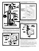
SURROUND INSTALLATION
The surround supplied with the insert is adjustable in
height so as to allow for many installation perimeters.
1. After the insert is in position, install left and right surround
sides by attaching them to the two side brackets using the
four 1/4-20 bolts provided. The retainer nuts on the
surround sides may be installed at any vertical position to
accommodate the installation.
2. Slide the surround top panel between the hopper top and
cover. Push the panel down until the screw holes align
with the side legs. Install the (4) #8 screws provided.
Install power cord into the receptacle on the right side of
the insert. Route cord behind surround leg and out to a
ground plus.
AUTOLITE INSTALLATION INSTRUCTIONS
The AutoLite System is factory installed with the only
installation requirements being the optional thermostat.
Wall Thermostat Installation:
The wall thermostat is designed to automatically regulate
the room temperature from the control panel heat setting to
the “Off” setting based upon room temperature. Remember
to leave the control panel on the "Medium or High" position
when utilizing the wall thermostat feature.
The following is a step by step procedure for installing the
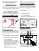
optional wall thermostat. Note connection terminals on left
side of unit at rear (Figure 7). Use 18/2 thermostat wire for
the installation.
a. Unplug heater from wall outlet and 12VDC power!
b. Remove factory jump wire and hook up thermostat
wires to terminals (Figure 7).
c. Locate thermostat approximately 10 to 12 feet from
heater or in area that requires steady temperature.
d. Run thermostat wires from heater to thermostat along
wall or under carpet etc. and hook wires to
thermostat terminals. On new construction you can,
of course, run wire in the walls before sheet rock or
paneling is done.
e. Reconnect AC power.
f. Make sure all wiring is completed before plugging the
EASYFIRE Heater back into the wall outlet.
IMPORTANT - Any electrical work performed on the
EASYFIRE Heater should be done by qualified personnel.
Remote Control Thermostat Installation:
The remote thermostat is designed to automatically
regulate the room temperature from the control panel heat
setting to the “Off” setting based upon room temperature
and placement of the remote thermostat. Remember to
leave the control panel on the "Medium or High" position
when utilizing the wall thermostat feature.
The following is a step by step procedure for installing the
optional remote thermostat. Note connection terminals on
rear of unit (Figure 7).
a. Unplug heater from wall outlet and 12VDC power!
b. Mount millivolt style remote receiver box to rear of
stove using double-sided tape.
b . Remove factory jump wire and hook up thermostat
wires to terminals (Figure 7).
d. Reconnect AC power and follow instructions with
remote thermostat regarding set up.
IMPORTANT - Any electrical work performed on the
EASYFIRE Heater should be done by qualified personnel.
DOOR HANDLE ASSEMBLY
The door handle and latch must be assembled and
adjusted prior to the operation of the stove.
1. Position handle assembly through door and secure with
collar by sliding over shaft and tightening with allen
wrench provided.
2. Position latch on end of shaft with flat facing allen screw.
Depending on gasket, shaft will protrude approx. 1/4"
through back of latch collar. Snug allen screw.
3. To adjust door, close and turn handle so latch contacts
striker. Door gasket must contact firmly against front face
of unit. This can be checked by closing against a piece of
paper. Firmly tug on paper, if it moves with solid
resistance the door is properly adjusted.