
User guide


WA_DEV_GL6100_PTS_001 Rev 004 November 30, 2010 36
GL61x0 Product Technical
Specification and User Guide
Interfaces and Peripherals
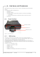
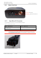
6.2. Back Interface
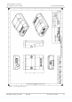
Figure 21. GL61x0 Back Interface
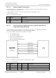
6.2.1. 8-pin Micro-Fit Connector
The 8-pin Micro-Fit connector is used for the following connections:
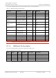
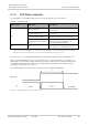
Table 21. 8-pin Micro-Fit Connections
GL6100 – UART Version
GL6110 – USB Version
External DC power supply connection with voltage
from +4.75V to +32V
External DC power supply connection with voltage 5V
Main serial link (RS-232)
USB connection
Caution: Bear in mind that the cables plugged into the 8-pin Micro-Fit connector should always be
compatible with the GL61x0 variant. Interchanging the cables between the two GL61x0 variants
(that is, using the RS-232 cable on the GL6110 or using the Micro-fit
®
USB cable on the GL6100)
may damage either the modem or the PC.
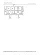
Figure 22. 8-pin Micro-Fit Connector on Cable Side
8-pin Micro-Fit Connector
RF Interface
1
2
3
4
5
7
8
6