
User guide


WA_DEV_GL6100_PTS_001 Rev 004 November 30, 2010 43
GL61x0 Product Technical
Specification and User Guide
Interfaces and Peripherals
Caution: GPIO19 is reserved for serial port auto shut down feature. It is prohibited for customer use.
Improper access to GPIO19 by customers may lead to unexpected behavior on serial port
performance.
It is prohibited to use the serial port auto shut down feature when the RS232-DTR is not used in the
application. Otherwise, there will be data lost from the DTE side to the GL6100.
6.2.1.3. Setup Communications with the GL6110: USB
Connection
The GL6110 has an embedded full speed USB 2.0 interface at 12Mbit/s. It could direct connect to the
PC USB port with the Micro-fit
®
to USB type A Cable.
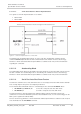
The signals on the Micro-fit
®
USB cable are as follows:
Vin, 5V (pin 1)
D- (pin 2)
D+ (pin 3)
GND (pin 4)
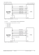
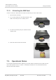
Figure 28. USB Signals on the USB Type A Connector
Refer to the following table for the USB pin description on the Micro-fit
®
connector.
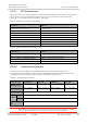
Table 25. USB Pin Description on Micro-fit
®
Connector
Pin #
Signal
Description
1
D+
Universal Serial Bus Data Positive
3
D-
Universal Serial Bus Data Negative
6.2.1.3.1. USB Driver
The USB Driver is available at http://www.sierrawireless.com/.
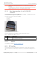
6.2.2. RF Interface
The GL61x0’s antenna connector allows the transmission of radio frequency (RF) signals from the
device to an external antenna. This interface is an FME type connector and its nominal impedance is
50Ω.
1
2
3
4