AirPrime HL7518 Product Technical Specification 4115834 9.
Product Technical Specification Important Notice Due to the nature of wireless communications, transmission and reception of data can never be guaranteed. Data may be delayed, corrupted (i.e., have errors) or be totally lost.
Product Technical Specification Patents This product may contain technology developed by or for Sierra Wireless Inc. This product is manufactured or sold by Sierra Wireless Inc. or its affiliates under one or more patents licensed from MMP Portfolio Licensing. Copyright © 2017 Sierra Wireless. All rights reserved. Trademarks Sierra Wireless®, AirPrime®, AirLink®, AirVantage®, WISMO®, ALEOS® and the Sierra Wireless and Open AT logos are registered trademarks of Sierra Wireless, Inc.
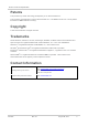
Product Technical Specification Document History Version Date Updates May 30, 2014 Creation • • June 05, 2014 Indicated that PCM pads are not available in Table 6 Pad Definition Updated: ▪ Table 6 Pad Definition ▪ Figure 3 Pad Configuration ▪ Table 20 Trace Debug Pad Description ▪ Section 5.6 ESD Guidelines for USB Removed: • ADC • section 5.6 Antenna Integration with Detection Circuit (due to the removal of ADC) 1.0 June 16, 2014 Updated: • 1.8.2 Regulatory • 3.10 POWER-ON Signal (PWR_ON_N) • 5.
Product Technical Specification Version Date Updates July 09, 2015 Updated: • Signal names from PWR_ON to PWR_ON_N, and RESET_IN to RESET_IN_N • Figure 2 Mechanical Overview • Table 6 Pad Definition • Figure 7 PWR_ON_N Sequence with VGPIO Information July 20, 2015 Updated: • Table 6 Pad Definition • Signal name from MIPI2_TRACE_CLK to TRACE_CLK 2.2 August 06, 2015 Updated: • Table 6 Pad Definition • 3.2 Current Consumption • Figure 7 PWR_ON_N Sequence with VGPIO Information 2.
Contents 1. INTRODUCTION ................................................................................................ 10 1.1. Common Flexible Form Factor (CF3) ..............................................................................10 1.2. Physical Dimensions .......................................................................................................10 1.3. General Features ............................................................................................................
Product Technical Specification 5. DESIGN GUIDELINES ....................................................................................... 33 5.1. Power-Up Sequence .......................................................................................................33 5.2. Module Switch-Off ...........................................................................................................34 5.3. Emergency Power OFF ...........................................................................
List of Figures Figure 1. Architecture Overview ..................................................................................................... 12 Figure 2. Mechanical Overview ...................................................................................................... 13 Figure 3. Pad Configuration ............................................................................................................ 20 Figure 4. Mechanical Drawing ...............................................
List of Tables Table 1. Supported Bands/Connectivity ........................................................................................ 10 Table 2. General Features ............................................................................................................ 11 Table 3. ESD Specifications .......................................................................................................... 14 Table 4. Environmental Specifications ..............................................
1. Introduction This document is the Product Technical Specification for the AirPrime HL7518 Embedded Module. It defines the high-level product features and illustrates the interfaces for these features. This document is intended to cover the hardware aspects of the product, including electrical and mechanical. The AirPrime HL7518 belongs to the AirPrime HL Series from Essential Connectivity Module family.
Product Technical Specification 1.3. Introduction General Features The table below summarizes the AirPrime HL7518 features. Table 2. General Features Feature Description • Physical • • • Small form factor (146-pad solderable LGA pad) – 23mm x 22mm x 2.5mm (nominal) Complete body shielding RF connection pads (RF main interface) Baseband signals connection Electrical Single or double supply voltage (VBATT and VBATT_PA) – 3.2V – 4.
Product Technical Specification Feature Introduction Description Multiple (up to 20) cellular packet data profiles Sleep mode for minimum idle power draw Mobile-originated PDP context activation / deactivation Support QoS profile ▪ Release 97 – Precedence Class, Reliability Class, Delay Class, Peak Throughput, Mean Throughput ▪ Release 99 QoS negotiation – Background, Interactive, and Streaming Static and Dynamic IP address.
Product Technical Specification 1.5. Introduction Interfaces The AirPrime HL7518 module provides the following interfaces and peripheral connectivity: • 1x - 8-wire UART • 1x - Active Low RESET • 1x - USB 2.0 • 1x - Backup Battery Interface • 2x - System Clock Out • 1x - Active Low POWER-ON • 1x - 1.8V/3V SIM • 1x - JTAG Interface • 14x - GPIOs (4 of which have multiplexes) • 1x - Main Antenna • 1x - RX Diversity • 1x - VGPIO 1.6.
Product Technical Specification 1.7. Introduction ESD Refer to the following table for ESD Specifications. Table 3. ESD Specifications Category Connection Specification Operational RF ports IEC-61000-4-2 — Level (Electrostatic Discharge Immunity Test) Non-operational Host connector interface Unless otherwise specified: • JESD22-A114 ± 2kV Human Body Model • JESD22-A115 ± 200V Machine Model • JESD22-C101C ± 250V Charged Device Model SIM connector Signals Other host signals 1.8.
Product Technical Specification 1.8.2. Introduction Regulatory The AirPrime HL7518 is compliant with FCC regulations. FCC compliance will be reflected on the AirPrime HL7518 label. Table 5. Regulation Compliance Document Current Version Title GCF-CC v3.51.1 or later GCF Conformance Certification Criteria FCC Part 27 NA Miscellaneous wireless communication services 1.8.3.
2. Pad Definition AirPrime HL7518 pads are divided into 2 functional categories. • Core functions and associated pads cover all the mandatory features for M2M connectivity and will be available by default across all CF 3 family of modules. These Core functions are always available and always at the same physical pad locations. A customer platform using only these functions and associated pads is guaranteed to be forward and/or backward compatible with the next generation of CF3 modules.
Product Technical Specification Pad Definition Pad # Signal Name 12 USB_D- 13 USB_D+ 14 NC Not Connected Not connected 15 NC Not Connected Not connected 16 USB_VBUS USB VBUS 17 NC 18 Function I/O USB Data Negative (Low / Full Speed) USB Data Negative (High Speed) USB Data Positive (Low / Full Speed) USB Data Positive (High Speed) Active Low/High Power Supply Domain 3.3V I/O 0.38V 3.3V I/O 0.
Product Technical Specification Pad Definition Pad # Signal Name Function I/O 35 PCM_SYNC* PCM sync out 36 PCM_CLK* 37 Power Supply Domain Recommendation for Unused Pads Type I/O 1.8V Left Open Extension PCM clock I/O 1.8V Left Open Extension GND Ground 0V 0V Mandatory connection Core 38 NC Not Connected (Reserved for future use) Left Open Not connected 39 GND Ground 0V 0V Mandatory connection Core 40 GPIO7 General purpose input/output I/O 1.
Product Technical Specification Pad Definition Pad # Signal Name Function I/O Active Low/High Power Supply Domain Recommendation for Unused Pads Type 59 PWR_ON_N Active Low Power On control signal I L 1.8V Mandatory connection Core 60 NC Not Connected (Reserved for future use) Left Open Not connected 61 VBATT_PA Power supply (refer to section 3.1 Power Supply for more information) I 3.2V (min) 3.7V (typ) 4.
Product Technical Specification 172 190 213 228 229 230 219 200 173 189 212 227 234 231 220 201 174 188 211 226 233 232 221 202 175 187 210 225 224 223 222 203 176 186 209 208 207 206 205 204 177 185 184 183 182 181 180 179 178 50 199 49 218 48 217 47 216 46 215 45 214 44 191 43 171 42 198 41 197 40 196 39 195 1 GND 66 65 64 63 62 61 60 59 58 57 56 55 54 53 52 GPIO5 UIM2_DET / GPIO4 UIM1_DET / GPIO3 VBATT VBATT_PA VBATT_PA NC PWR_O
3. Detailed Interface Specifications Note: If not specified, all electrical values are given for VBATT=3.7V and an operating temperature of 25°C. VBATT and VBATT_PA must be tied externally to the same power supply. 3.1. Power Supply The AirPrime HL7518 module is supplied through the VBATT signal with the following characteristics. Table 7. Power Supply Supply Minimum Typical Maximum VBATT voltage (V) 3.2* 3.7 4.5 VBATT_PA voltage (V) Full Specification 3.2* 3.7 4.
Product Technical Specification 3.3. Detailed Interface Specifications VGPIO The VGPIO output can be used to: • Pull-up signals such as I/Os • Supply the digital transistors driving LEDs The VGPIO output is available when the AirPrime HL7518 module is switched ON. Table 9. VGPIO Electrical Characteristics Parameter Minimum Typical Maximum Remarks Voltage level (V) 1.7 1.8 1.
Product Technical Specification 3.5. Detailed Interface Specifications SIM Interface The AirPrime HL7518 has one physical SIM interface, UIM1. It allows control of a 1.8V/3V SIM and is fully compliant with GSM 11.11 recommendations concerning SIM functions. The five signals used by UIM1 are as follows: • UIM1_VCC: power supply • UIM1_CLK: clock • UIM1_DATA: I/O port • UIM1_RESET: reset • UIM1_DET: SIM detection Table 11. UIM1 Pad Description Pad # Signal Name Description 26 UIM1_VCC 1.
Product Technical Specification 3.6. Detailed Interface Specifications USB The AirPrime HL7518 has one USB interface. Table 13. USB Pad Description Pad Number Signal Name I/O Function 12 USB_D- I/O USB Data Negative 13 USB_D+ I/O USB Data Positive 16 USB_VBUS I USB VBUS Note: When a USB supply is not available, connect USB_VBUS to VBATT to supply the USB interface. USB_VBUS will have a voltage range of 3.3V to 4.5V when connected to VBATT. 3.7.
Product Technical Specification 3.8. Detailed Interface Specifications General Purpose Input/Output (GPIO) The AirPrime HL7518 modules provide 14 GPIOs, 4 of which have multiplexes. Table 15. GPIO Pad Description Pad # Signal Name 1 GPIO1 10 GPIO2 40 GPIO7 41 GPIO8 44 I/O Power Supply Domain I/O 1.8V I/O 1.8V I/O 1.8V I/O 1.8V GPIO13 I/O 1.8V 46 GPIO6 I/O 1.8V 51 GPIO14 I/O 1.8V 52 GPIO10 I/O 1.8V 53 GPIO11 I/O 1.8V 54 GPIO15 I/O 1.8V 58 GPIO12 I/O 1.
Product Technical Specification Table 16. Detailed Interface Specifications UART1 Pad Description Pad # Signal Name* I/O* Description 2 UART1_RI O Signal incoming calls (data only), SMS, etc.
Product Technical Specification Detailed Interface Specifications 3.11. Reset Signal (RESET_IN_N) To reset the module, a low-level pulse must be sent on the RESET_IN_N pad for 20ms. This action will immediately restart the AirPrime HL7518 module with the PWR_ON_N signal at low level. (If the PWR_ON_N signal is at high level, the module will be powered off.) As RESET_IN_N is internally pulled up, an open collector or open drain transistor has to be used to control this signal.
Product Technical Specification Detailed Interface Specifications 3.13. Debug Interfaces The AirPrime HL7518 module provides 2 interfaces for a powerful debug system. 3.13.1. Trace Debug The AirPrime HL7518 module provides a Trace Debug interface, providing real-time instruction and data trace of the modem core. Table 20.
Product Technical Specification Detailed Interface Specifications 3.14. RF Interface The RF interface of the HL7518 module allows the transmission of RF signals. This interface has a 50Ω nominal impedance. 3.14.1. RF Connection A 50Ω stripline can be used to connect to standard RF connectors such as SMA, UFL, etc. for antenna connection. Table 22. RF Main Connection Pad Number RF Signal Impedance VSWR Rx (max) VSWR Tx (max) 49 RF_MAIN 50Ω 1.5:1 1.5:1 Table 23.
4. Mechanical Drawings Figure 4. 4115834 Mechanical Drawing Rev 9.
Product Technical Specification Figure 5. 4115834 Mechanical Drawings Dimensions Drawing Rev 9.
Product Technical Specification Figure 6. 4115834 Mechanical Drawings Footprint Rev 9.
5. Design Guidelines 5.1. Power-Up Sequence Apply a low-level logic to the PWR_ON_N pad (pad 59); within approximately 25ms, VGPIO will appear to be at 1.8V. Either UART1 or the USB interface could be used to send AT commands. The AT command interface is available in about 7 seconds after PWR_ON_N for either UART or USB. When using UART, the AT command interface is available after the transition of UART1_CTS from high to low level.
Product Technical Specification 5.2. Design Guidelines Module Switch-Off AT command AT+CPWROFF enables the user to properly switch the AirPrime HL7518 module off. AT+CPWROFF Module is ON PWR_ON_N Internal pull-up to 1V8 Module is OFF 2 seconds VGPIO Figure 8. Power OFF Sequence for PWR_ON_N, VGPIO Note: PWR_ON_N is internally pulled up by 100kΩ to 1.8V. 5.3. Emergency Power OFF If required, the module can be switched off by controlling the RESET_IN_N pad (pad 11).
Product Technical Specification 5.5. Design Guidelines ESD Guidelines for SIM Card Decoupling capacitors must be added according to the drawings below as close as possible to the SIM card connectors on UIM1_CLK, UIM1_RST, UIM1_VCC, UIM1_DATA and UIM1_DET signals to avoid EMC issues and to comply with the requirements of ETSI and 3GPP standards covering the SIM electrical interface. A typical schematic including SIM detection is provided below. Figure 10.
Product Technical Specification 5.6. Design Guidelines ESD Guidelines for USB When the USB interface is externally accessible, it is required to have ESD protection on the USB_VBUS, USB_D+ and USB_D- signals. Figure 11. Note: ESD Protection for USB It is not recommended to have an ESD diode with feedback path from USB_VBUS to either USB_D+ or USB_D-. Sierra Wireless recommends using a 90Ω DLP0NSN900HL2L EMC filter and an RCLAMP0503N or ESD5V3U2U-03LRH ESD diode. 4115834 Rev 9.
6. Reliability Specification AirPrime HL7518 modules are tested against the Sierra Wireless Industrial Reliability Specification defined below. 6.1. Reliability Compliance The AirPrime HL7518 module connected on a development kit board application is compliant with the following requirements. Table 25. Standards Conformity Abbreviation Definition IEC International Electro technical Commission ISO International Organization for Standardization 6.2. Reliability Prediction Model 6.2.1.
Product Technical Specification 6.2.2. Reliability Specification Environmental Resistance Stress Tests The following tests the AirPrime HL7518 module’s resistance to extreme temperature. Table 27.
Product Technical Specification Reliability Specification Designation Condition Component Solder Wettability CSW Standard: JESD22 – B102, Method 1/Condition C, Solderability Test Method Special conditions: Test method: Dip and Look Test with Steam preconditioning 8 h ± 15min. dip for 5 +0/-0.
Product Technical Specification 6.2.5. Reliability Specification Mechanical Resistance Stress Tests The following tests the AirPrime HL7518 module’s resistance to vibrations and mechanical shocks. Table 30. Mechanical Resistance Stress Tests Designation Condition Standard: IEC 60068-2-6, Test Fc Sinusoidal Vibration Test SVT Special conditions: • Frequency range: 16 Hz to 1000 Hz • Displacement: 0.
Product Technical Specification 6.2.6. Reliability Specification Handling Resistance Stress Tests The following tests the AirPrime HL7518 module’s resistance to handling malfunctions and damage. Table 31.
7. FCC Legal Information The HL7518 module has been granted modular approval for mobile applications. Integrators may use the HL7518 module in their final products without additional FCC certification if they meet the following conditions. Otherwise, additional FCC approvals must be obtained. 1. At least 20 cm separation distance between the antenna and the user’s body must be maintained at all times. 2.
Product Technical Specification FCC Legal Information If a multi-layered PCB is used, the RF path on the board must not cross any signal (digital, analog or supply). If necessary, use StripLine structure and route the digital line(s) "outside" the RF structure. An example of proper routing is shown in the figure below. Stripline and Coplanar design requires having a correct ground plane at both sides. Consequently, it is necessary to add some vias along the RF path.
8. Ordering Information Table 32. Ordering Information Model Name Description Part Number HL7518 HL7518 embedded module Contact Sierra Wireless for the latest SKU DEV-KIT HL Series Development Kit 6000620 4115834 Rev 9.
9.
Product Technical Specification Terms and Abbreviations Abbreviation Definition RF Radio Frequency RFI Radio Frequency Interference RMS Root Mean Square RST Reset RTC Real Time Clock RX Receive SCL Serial Clock SDA Serial Data SIM Subscriber Identification Module SMD Surface Mounted Device/Design SPI Serial Peripheral Interface SW Software PSRAM Pseudo Static RAM TBC To Be Confirmed TBD To Be Defined TP Test Point TX Transmit TYP Typical UART Universal Asynchronous R