
AirPrime IoT Module Technical Specification Rev9 0

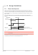

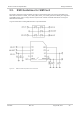
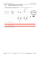

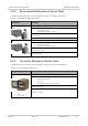
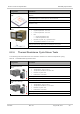
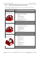
Table Of Contents
- Contents
- List of Figures
- List of Tables
- 1. Introduction
- 2. Pad Definition
- 3. Detailed Interface Specifications
- 3.1. Power Supply
- 3.2. Current Consumption
- 3.3. VGPIO
- 3.4. BAT_RTC
- 3.5. SIM Interface
- 3.6. USB
- 3.7. Electrical Information for Digital I/O
- 3.8. General Purpose Input/Output (GPIO)
- 3.9. Main Serial Link (UART1)
- 3.10. POWER-ON Signal (PWR_ON_N)
- 3.11. Reset Signal (RESET_IN_N)
- 3.12. Clock Interface
- 3.13. Debug Interfaces
- 3.14. RF Interface
- 4. Mechanical Drawings
- 5. Design Guidelines
- 6. Reliability Specification
- 7. FCC Legal Information
- 8. Ordering Information
- 9. Terms and Abbreviations

4115834 Rev 9.0 August 28, 2017 34
Product Technical Specification
Design Guidelines
5.2. Module Switch-Off
AT command AT+CPWROFF enables the user to properly switch the AirPrime HL7518 module off.
2 seconds
AT+CPWROFF
Module is ON
PWR_ON_N
Internal pull-up to
1V8
Module is OFF
VGPIO
Figure 8. Power OFF Sequence for PWR_ON_N, VGPIO
Note: PWR_ON_N is internally pulled up by 100kΩ to 1.8V.
5.3. Emergency Power OFF
If required, the module can be switched off by controlling the RESET_IN_N pad (pad 11). This must
only be used in emergency situations if the system freezes (not responding to AT commands).
To perform an emergency power off, a low-level pulse must be sent on the RESET_IN_N pad for
20ms while the PWR_ON_N signal is inactive (high level). This action will immediately shut the
HL7518 module down and the registers of the CPU and RAM memory will be reset for the next power
on.
5.4. Power Supply Design
The AirPrime HL7518 module should not be supplied with voltage over 4.5V even temporarily or
however briefly.
If the system’s main board power supply unit is unstable or if the system’s main board is supplied with
over 4.5V, even in the case of transient voltage presence on the circuit, the module’s power amplifier
may be severely damaged.
To avoid such issues, add a voltage limiter to the module’s power supply lines so that VBATT and
VBATT_PA signal pads will never receive a voltage surge over 4.5V. The voltage limiter can be as
simple as a Zener diode with decoupling capacitors as shown in the diagram below.
Power Supply
VBATT/VBATT_PA
D404
0.5 pF
D405
C404
1.5 mF
+
+
C405
150 µF
C407
100 nF
Figure 9. Voltage Limiter Example