Product Technical Specification AirPrime HL7690 4118552 5.
Product Technical Specification Important Notice Due to the nature of wireless communications, transmission and reception of data can never be guaranteed. Data may be delayed, corrupted (i.e., have errors) or be totally lost.
Product Technical Specification Patents This product may contain technology developed by or for Sierra Wireless Inc. This product includes technology licensed from QUALCOMM®. This product is manufactured or sold by Sierra Wireless Inc. or its affiliates under one or more patents licensed from InterDigital Group and MMP Portfolio Licensing. Copyright © 2016 Sierra Wireless. All rights reserved.
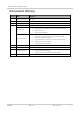
Product Technical Specification Document History Version Date Updates 1.0 January 21, 2016 Creation 1.1 January 26, 2016 Removed FCC references, added CE 1.2 February 16, 2016 Updated Table 2 General Features June 06, 2016 Added 5.5 Power Supply Design July 05, 2016 Updated: Figure 2 Mechanical Overview (Top View and Bottom View) 3.
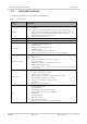
Contents 1. INTRODUCTION .................................................................................................. 9 1.1. Common Flexible Form Factor (CF3) ................................................................................ 9 1.2. Physical Dimensions ......................................................................................................... 9 1.3. General Features ........................................................................................................
Product Technical Specification 4. MECHANICAL DRAWINGS ............................................................................... 30 5. DESIGN GUIDELINES ....................................................................................... 33 5.1. Power-Up Sequence .......................................................................................................33 5.2. Module Switch-Off ..........................................................................................................
List of Figures Figure 1. Architecture Overview ..................................................................................................... 11 Figure 2. Mechanical Overview (Top View and Bottom View) ....................................................... 12 Figure 3. Pad Configuration ............................................................................................................ 19 Figure 4. TX_ON State During Transmission ......................................................
List of Tables Table 1. Supported Bands/Connectivity .......................................................................................... 9 Table 2. General Features ............................................................................................................ 10 Table 3. ESD Specifications .......................................................................................................... 13 Table 4. Environmental Specifications .............................................
1. Introduction This document is the Product Technical Specification for the AirPrime HL7690 Embedded Module. It defines the high level product features and illustrates the interfaces for these features. This document is intended to cover the hardware aspects of the product, including electrical and mechanical. The AirPrime HL7690 belongs to the AirPrime HL Series from Essential Connectivity Module family.
Product Technical Specification 1.3. Introduction General Features The table below summarizes the AirPrime HL7690 features. Table 2. General Features Feature Description Physical Small form factor (146-pad solderable LGA pad) – 23mm x 22mm x 2.5mm (nominal) Complete body shielding (molded module using an overmoulding compound and metal sputtering). Note that molded HL7690 modules are prototypes and that module body shielding is subject to change.
Product Technical Specification Feature Introduction Description Connectivity Operating temperature ranges (industrial grade): Class A: -30°C to +70°C Environmental RTC 1.4.
Product Technical Specification 1.5. Introduction Interfaces The AirPrime HL7690 module provides the following interfaces and peripheral connectivity: 1x - 8-wire UART 1x - Active Low RESET 1x - USB 2.0 1x - Backup Battery Interface 2x - System Clock Out 1x - Active Low POWER-ON 1x - 1.
Product Technical Specification 1.7. Introduction ESD Refer to the following table for ESD specifications. Table 3. ESD Specifications Category Connection Specification Operational RF ports IEC-61000-4-2 — Level (Electrostatic Discharge Immunity Test) Non-operational Host connector interface Unless otherwise specified: JESD22-A114 ± 1kV Human Body Model JESD22-A115 ± 200V Machine Model SIM connector Signals Other host signals 1.8.
Product Technical Specification 1.8.2. Introduction Regulatory Sierra Wireless hereby declares that the HL7690 is in compliance with all essential requirements of R&TTE Directive 1999/5/EC. The Declaration of Conformity will be available for viewing at the following location in the EU community: Sierra Wireless (UK) Limited Suite 5, The Hub Fowler Avenue Farnborough Business Park Farnborough, United Kingdom GU14 7JP 1.8.3.
2. Pad Definition AirPrime HL7690 pads are divided into 2 functional categories. Core functions and associated pads cover all the mandatory features for M2M connectivity and will be available by default across all CF 3 family of modules. These Core functions are always available and always at the same physical pad locations. A customer platform using only these functions and associated pads is guaranteed to be forward and/or backward compatible with the next generation of CF3 modules.
Product Technical Specification Pad Definition Pad # Signal Name Function I/O Active Low/High Power Supply Domain Recommendation for Unused Pads Type 11 RESET_IN_N Input reset signal I L 1.
Product Technical Specification Pad Definition Power Supply Domain Recommendation for Unused Pads Type I 1.8V Left Open Extension PCM sync out I/O 1.8V Left Open Extension PCM_CLK* PCM clock I/O 1.8V Left Open Extension 37 GND Ground 0V 0V Mandatory connection Core 38 NC Not Connected (Reserved for future use) Left Open Not connected 39 GND Ground 0V 0V Mandatory connection Core 40 GPIO7 General purpose input/output I/O 1.
Product Technical Specification Pad Definition Pad # Signal Name Function I/O Active Low/High Power Supply Domain Recommendation for Unused Pads Type 59 PWR_ON_N Active Low Power On control signal I L 1.8V Mandatory connection Core 60 TX_ON TX indicator O 2.3V Left Open Extension 61 VBATT_PA Power supply (refer to section 3.1 Power Supply for more information) I 3.2V (min) 3.7V (typ) 4.5V (max) Mandatory connection Core 62 VBATT_PA Power supply (refer to section 3.
Product Technical Specification 217 218 199 172 190 213 228 229 230 219 200 173 189 212 227 234 231 220 201 174 188 211 226 233 232 221 202 175 187 210 225 224 223 222 203 176 186 209 208 207 206 205 204 177 185 184 183 182 181 180 179 178 50 216 49 215 47 47 48 214 46 191 45 171 44 198 42 42 43 43 197 41 196 40 195 38 38 39 194 37 193 1 GND 66 65 64 63 62 61 60 59 58 58 57 57 56 56 55 55 54 53 52 GPIO5 GPIO4 UIM1_DET VBATT VBATT_
3. Detailed Interface Specifications Note: If not specified, all electrical values are given for VBATT=3.7V and an operating temperature of 25°C. For standard applications, VBATT and VBATT_PA must be tied externally to the same power supply. For some specific applications, AirPrime HL7690 module supports separate VBATT and VBATT_PA connection if requirements below are fulfilled. 3.1. Power Supply The AirPrime HL7690 module is supplied through the VBATT signal with the following characteristics. Table 6.
Product Technical Specification Table 8. Detailed Interface Specifications Current Consumption per Power Supply Parameter (at nominal voltage, 3.7 V) LTE in communication mode (TX Max) USB = disconnected VBATT LTE in communication mode (TX Max) USB = disconnected VBATT_PA 3.3.
Product Technical Specification 3.5. Detailed Interface Specifications SIM Interface The AirPrime HL7690 has one physical SIM interface, UIM1, which has optional support for dual SIM application with an external SIM switch. It allows control of a 1.8V/3V SIM and is fully compliant with GSM 11.11 recommendations concerning SIM functions.
Product Technical Specification 3.6. Detailed Interface Specifications USB The AirPrime HL7690 has one USB interface. Table 13. USB Pad Description Pad Number Signal Name I/O Function 12 USB_D- I/O USB Data Negative 13 USB_D+ I/O USB Data Positive 16 USB_VBUS I USB VBUS Note: When the 5V USB supply is not available, connect USB_VBUS to VBATT to supply the USB interface. 3.7.
Product Technical Specification 3.8. Detailed Interface Specifications General Purpose Input/Output (GPIO) The AirPrime HL7690 modules provide 12 GPIOs, 2 of which have multiplexes. Table 15. GPIO Pad Description Pad # Signal Name 1 GPIO1 10 GPIO2 40 GPIO7 41 GPIO8 44 I/O Power Supply Domain I/O 1.8V I/O 1.8V I/O 1.8V I/O 1.8V GPIO13 I/O 1.8V 46 GPIO6 I/O 1.8V 51 GPIO14 I/O 1.8V 52 GPIO10 I/O 1.8V 53 GPIO11 I/O 1.8V 54 GPIO15 I/O 1.8V 65 GPIO4 I/O 1.
Product Technical Specification Table 16. Detailed Interface Specifications UART1 Pad Description Pad # Signal Name* I/O* Description 2 UART1_RI O Signal incoming calls (data only), SMS, etc.
Product Technical Specification Detailed Interface Specifications The RESET_IN_N signal will reset the registers of the CPU and reset the RAM memory as well, for the next power on. As RESET_IN_N is referenced to the VRTC (200kΩ pull-up resistor to VRTC 1.8V) an open collector or open drain transistor has to be used to control this signal. Note: Table 18. RESET_IN_N Electrical Characteristics Parameter Minimum Input Voltage-Low (V) Typical Maximum - 0.51 Input Voltage-High (V) 1.33 - 2.
Product Technical Specification Detailed Interface Specifications 3.13. Clock Interface The AirPrime HL7690 modules support two digital clock interfaces. The following table describes the pad description of the clock out interfaces. Table 21. Clock Interface Pad Description Pad Number Signal Name I/O I/O Type Description 22 26M_CLKOUT O 1.8V 26MHz Digital Clock output 23 32K_CLKOUT O 1.8V 32.
Product Technical Specification Detailed Interface Specifications Pad Number Signal Name Function 239 JTAG_TMS JTAG Test Mode Select 240 JTAG_TRST JTAG Test Reset 241 JTAG_TDI JTAG Test Data Input 242 JTAG_RTCK JTAG Returned Test Clock Note: It is recommended to provide access through Test Points to this interface the JTAG pads (for Failure Analysis debugging). All signals listed in table above shall be outputs on the customer board to allow JTAG debugging. 3.15.
Product Technical Specification Detailed Interface Specifications 3.15.2. RF Performances RF performances are compliant with 3GPP recommendation TS 36.101. Table 26.
4. Mechanical Drawings Figure 5. 4118552 Mechanical Drawing Rev 5.
Product Technical Specification Figure 6. 4118552 Mechanical Drawings Dimensions Drawing Rev 5.
Product Technical Specification Figure 7. 4118552 Mechanical Drawings Footprint Rev 5.
5. Design Guidelines 5.1. Power-Up Sequence Apply a LOW level logic to the PWR_ON_N pad (pad 59); within approximately 25ms, VGPIO will appear to be at 1.8V. Either UART1 or the USB interface could be used to send AT commands. The AT command interface is available in about 7 seconds after PWR_ON_N for either UART or USB. When using UART, the AT command interface is available after the transition of UART1_CTS from high to low level.
Product Technical Specification 5.3. Design Guidelines Emergency Power OFF If required, the module can be switched off by controlling the RESET_IN_N pad (pad 11). This must only be used in emergency situations if the system freezes (not responding to AT commands). To perform an emergency power off, a low level pulse must be sent on the RESET_IN_N pad for 20ms while the PWR_ON_N signal is inactive (high level).
Product Technical Specification Design Guidelines Power Supply Figure 10. 5.6. + C405 150 µF C407 100 nF + C404 1.5 mF D405 D404 0.
Product Technical Specification 5.7. Design Guidelines ESD Guidelines for USB When the USB interface is externally accessible, it is required to have ESD protection on the USB_VBUS, USB_D+ and USB_D- signals. Figure 12. Note: ESD Protection for USB It is not recommended to have an ESD diode with feedback path from USB_VBUS to either USB_D+ or USB_D-. Sierra Wireless recommends using a 90Ω DLP0NSN900HL2L EMC filter and an RCLAMP0503N or ESD5V3U2U-03LRH ESD diode. 4118552 Rev 5.
6. Reliability Specification AirPrime HL7690 modules are tested against the Sierra Wireless Industrial Reliability Specification defined below. 6.1. Reliability Compliance AirPrime HL7690 modules connected on a development kit board application are compliant with the following requirements. Table 29. Standards Conformity Abbreviation Definition IEC International Electro technical Commission ISO International Organization for Standardization 6.2. Reliability Prediction Model 6.2.1.
Product Technical Specification 6.2.2. Reliability Specification Environmental Resistance Stress Tests The following tests the AirPrime HL7690 module’s resistance to extreme temperature. Table 31.
Product Technical Specification Reliability Specification Designation Condition Component Solder Wettability CSW Standard: JESD22 – B102, Method 1/Condition C, Solderability Test Method Special conditions: Test method: Dip and Look Test with Steam preconditioning 8 h ±15min. dip for 5 +0/-0.
Product Technical Specification 6.2.5. Reliability Specification Mechanical Resistance Stress Tests The following tests the AirPrime HL7690 module’s resistance to vibrations and mechanical shocks. Table 34. Mechanical Resistance Stress Tests Designation Condition Standard: IEC 60068-2-6, Test Fc Sinusoidal Vibration Test SVT Special conditions: Frequency range: 16 Hz to 1000 Hz Displacement: 0.
Product Technical Specification 6.2.6. Reliability Specification Handling Resistance Stress Tests The following tests the AirPrime HL7690 module’s resistance to handling malfunctions and damage. Table 35.
7. Ordering Information Table 36. Ordering Information Model Name Description Part Number HL7690 HL7690 embedded module Contact Sierra Wireless for the latest SKU DEV-KIT HL Series Development Kit 6000620 4118552 Rev 5.
8.
Product Technical Specification Terms and Abbreviations Abbreviation Definition RF Radio Frequency RFI Radio Frequency Interference RMS Root Mean Square RST Reset RTC Real Time Clock RX Receive SCL Serial Clock SDA Serial Data SIM Subscriber Identification Module SMD Surface Mounted Device/Design SPI Serial Peripheral Interface SW Software PSRAM Pseudo Static RAM TBC To Be Confirmed TBD To Be Defined TP Test Point TX Transmit TYP Typical UART Universal Asynchronous R