CDMA and GSM / UMTS Mini Card Hardware Integration Guide Proprietary and Confidential Includes: MC5725 MC8775 MC5725V MC8775V MC5727 MC8780 MC5727V MC8781 MC5728V MC8790 MC8790V MC8791V MC8792V MC8795V MC8700 2130114 Rev 1.12.
Preface Important Notice Due to the nature of wireless communications, transmission and reception of data can never be guaranteed. Data may be delayed, corrupted (i.e., have errors) or be totally lost.
CDMA and GSM / UMTS Mini Card Hardware Integration Guide REVENUE OR ANTICIPATED PROFITS OR REVENUE ARISING OUT OF THE USE OR INABILITY TO USE ANY SIERRA WIRELESS PRODUCT, EVEN IF SIERRA WIRELESS AND/OR ITS AFFILIATES HAS BEEN ADVISED OF THE POSSIBILITY OF SUCH DAMAGES OR THEY ARE FORESEEABLE OR FOR CLAIMS BY ANY THIRD PARTY.
Preface Contact Information Sales Desk: Phone: 1-604-232-1488 Hours: 8:00 AM to 5:00 PM Pacific Time E-mail: sales@sierrawireless.com Post: Sierra Wireless 13811 Wireless Way Richmond, BC Canada V6V 3A4 Fax: 1-604-231-1109 Web: www.sierrawireless.com Consult our website for up‐to‐date product descriptions, documentation, application notes, firmware upgrades, trouble‐ shooting tips, and press releases: www.sierrawireless.com Rev 1.12.4 Oct.
CDMA and GSM / UMTS Mini Card Hardware Integration Guide 6 Proprietary and Confidential 2130114 In the event of a discrepancy in values between this guide and the Product Specification Document (PSD), the PSD takes precedence.
Table of Contents Introduction . . . . . . . . . . . . . . . . . . . . . . . . . . . . . . . . . . . . . . . . . . . . . . .9 The Universal Development Kit . . . . . . . . . . . . . . . . . . . . . . . . . . . . . . . . . . . . . . 9 Required connectors . . . . . . . . . . . . . . . . . . . . . . . . . . . . . . . . . . . . . . . . . . . . . . 10 Guide organization . . . . . . . . . . . . . . . . . . . . . . . . . . . . . . . . . . . . . . . . . . . . . . . . 10 Related documents. . . . . . . . . . . . . .
CDMA and GSM / UMTS Mini Card Hardware Integration Guide System block diagrams . . . . . . . . . . . . . . . . . . . . . . . . . . . . . . . . . . . . . . . . . Modes of operation . . . . . . . . . . . . . . . . . . . . . . . . . . . . . . . . . . . . . . . . . . . . Sidetone support . . . . . . . . . . . . . . . . . . . . . . . . . . . . . . . . . . . . . . . . . . . . . . Echo cancellation support . . . . . . . . . . . . . . . . . . . . . . . . . . . . . . . . . . . . . . Audio signal interface . . . . .
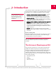
1 1: Introduction Sierra Wireless’ Mini Card modules form the radio component for the products in which they are embedded. Mini Cards are available for use on CDMA and GSM networks, including: Note: Throughout this document, MC57xx and MC87xx refer to the entire suites of CDMA and GSM Mini Cards respectively. • MC5725 / MC5725V / MC5727 / MC5727V / MC5728V—Operate on CDMA networks using the CDMA IS‐95A, 1X, and 1xEV‐DO (IS‐856) network standards, and support GPS.
CDMA and GSM / UMTS Mini Card Hardware Integration Guide For instructions on setting up the UDK, see PCI Express Mini Card Dev Kit Quick Start Guide (Document 2130705). Required connectors Note: Contact vendors before choosing your connectors — the numbers included here are for reference only. Choose connectors that are appropriate to your design. When integrating these modules into your host device, you need the following connector types: • RF cables that mate with Hirose U.FL connectors (model U.
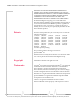
Introduction Related documents This guide deals specifically with hardware integration issues that are unique to the MC57xx and MC87xx modules. Table 1‐1 lists other documents referenced in this guide. Table 1-1: Related documentation Document title Description AT Command Set for User Equipment (UE) (Release 6) Standard AT commands for GSM / UMTS devices. CDMA 1X Standard Technical requirements for CDMA systems, including details on sleep cycle index (SCI) values. Download this document (3GPP TS 27.
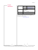
CDMA and GSM / UMTS Mini Card Hardware Integration Guide Table 1-1: Related documentation (Continued) Document title 12 Description MC5727 Mini Card Product Specification (Document 2130958) Features, mechanical and electrical specifications, and standards compliance of the MC5727. MC5727V Mini Card Product Specification (Document 2131023) Features, mechanical and electrical specifications, and standards compliance of the MC5727V.
Introduction Table 1-1: Related documentation (Continued) Document title Description MC87xx Modem CnS Reference (Voice) (Document 2130817) Voice-related CnS (Control and Status) messages supported by the MC8775V, MC8790V,MC8791V, and MC8792V, and MC8795V. UMTS Modems Supported AT Command Reference (Document 2130617) Proprietary, basic AT commands for the MC87xx. For MC57xx-specific commands, see the CDMA AT Command Reference (Document 2130620).
CDMA and GSM / UMTS Mini Card Hardware Integration Guide 14 Proprietary and Confidential 2130114 In the event of a discrepancy in values between this guide and the Product Specification Document (PSD), the PSD takes precedence.
2 2: Power Interface Overview of operation Note: This chapter contains information for CDMA (MC57xx) and GSM (MC87xx) modules. Information that is unique to specific module types is clearly identified. The module is designed to use a 3.3V (nominal) power supply, provided by the host. It is the host’s responsibility to provide safe and continuous power to the module at all times; the module does NOT have an independent power supply, or protection circuits to guard against electrical issues.
CDMA and GSM / UMTS Mini Card Hardware Integration Guide MC5728V has placeholders for additional ESD devices, for cases where the device must, per customer requirements, meet the higher Human Body Model (+/‐1kV) ESD rating. Specific recommendations are provided where needed in this guide, however, the level of protection required depends on your application.
Power Interface Off state In this state, the host is powered up and the module is powered down (but still connected to the power source). The host keeps the module powered off by driving the W_Disable# signal low. In this state, the module draws minimal current. Normal state Note: This is the default state when VCC3.3 is first applied in the absence of W_Disable# control. This is the active state of the module. In this state: • The module is fully powered.
CDMA and GSM / UMTS Mini Card Hardware Integration Guide Table 2-1: Power consumption of a sample application (Continued) Used by a field worker (data only) Used for remote data logging Hours of operation 8/day (off 16 hrs/day) 24/day Total power consumed over 24 hours 60 mAh 200 mAh This example model applies to a battery‐operated device.
3 3: RF Integration The MC87xx operates on the frequencies detailed in Table 3‐1. Table 3-1: MC87xx— RF parameters Product Rev 1.12.4 Oct.
CDMA and GSM / UMTS Mini Card Hardware Integration Guide Table 3-1: MC87xx— RF parameters (Continued) Product Band Frequencies (MHz) MC8792V MC8795V MC8700 Band VIII UMTS 900 (0.1%) 12.2 kbps Tx: 880–915 Rx: 925–960 MC8775V MC8780 MC8781 MC8790 MC8790V MC8791V MC8792V MC8795V GPS 1575.42 RF connection When attaching an antenna to the module: Note: To disconnect the antenna, make sure you use the Hirose U.
RF Integration Figure 3-1: Antenna connection points and mounting holes Ground connection When connecting the module to system ground: • Prevent noise leakage by establishing a very good ground connection to the module through the host connector. • Connect to system ground using the two mounting holes at the top of the module (as shown in Figure 3‐1). • Minimize ground noise leakage into the RF. Depending on the host board design, noise could potentially be coupled to the module from the host board.
CDMA and GSM / UMTS Mini Card Hardware Integration Guide Shielding The module is fully shielded to protect against EMI and to ensure compliance with FCC Part 15 ‐ “Radio Frequency Devices” (or equivalent regulations in other jurisdictions). Note: The module shields must NOT be removed.
RF Integration • Antenna cables should be routed, if possible, away from noise sources (switching power supplies, LCD assemblies, etc.). If the cables are near the noise sources, the noise may be coupled into the RF cable and into the antenna. Disabling the diversity antenna • MC57xx — If your host device is not designed to use the MC57xx module’s diversity antenna, terminate the interface with a 50 Ω load.
CDMA and GSM / UMTS Mini Card Hardware Integration Guide The severity of this interference depends on the closeness of the other antennas to the module’s antenna. To determine suitable locations for each wireless device’s antenna, thoroughly evaluate your host device’s design. Device-generated RF All electronic computing devices generate RF interference that can negatively affect the receive sensitivity of the module.
4 4: Audio Interface The MC5725V / MC5727V / MC5728V / MC8775V / MC8790V / MC8791V / MC8792V / MC8795V modules support six audio modes that may be required by a host audio system: • Handset • Headset • Car kit • Speakerphone • AUX (MC5727V / MC5728V modules are preconfigured for HAC [Hearing Aid Compatibility]) • TTY Note: Values in this guide are taken from the appropriate product specification documents (PSDs) (listed in Related documents, page 11) — in the case of a discrepancy between this document an
CDMA and GSM / UMTS Mini Card Hardware Integration Guide Table 4-1: Audio features (Continued) Feature FIR (Finite Impulse Response) filtering Transmit Receive MC87xx: • Option of providing 13 tap FIR filtering for receive and transmit paths to equalize the acoustic response of the speaker and microphone elements. Audio pass band 300 Hz–3.
Audio Interface • Dynamic ranges for each programmable gain stage are Note: Make sure the host device includes DC blocking capacitors on the Audio In lines – the module does not include series capacitors.
CDMA and GSM / UMTS Mini Card Hardware Integration Guide Figure 4-2: MC5728V Audio system block g TX ADC 57.
Audio Interface Note: Data mixing is not supported. If mixing of voice signal is required, it must be done by the host processor. Figure 4-3: MC8775V /MC8790V / MC8791V / MC8792V / MC8795V Audio system block PCM Audio interface MIC_P TX_HPF_DIS_N TX_SLOPE_FILT_DIS_N MIC_N 57.3mVrms @ 0dBm0 HPF & Slope NS & AAGC +12dB -3dB -84dB TxPCMFilt TxVolume Tx FIR 13K CELP/ EVRC Encoder +12dB 0dB -84dB MIC_AMP1_GAIN -6dB to +49.5dB in 1.
CDMA and GSM / UMTS Mini Card Hardware Integration Guide The typical handset sidetone is 12 dB below transmit voice levels. For Handset and Headset mode, the threshold of pain (+120 dBSPL) must not be exceeded at the maximum volume setting. A good target for the medium volume setting is +94 dBSPL, as this is a typical level for conversational speech. Most audio gain should be added to the host audio front end (within the PDA style codec gain blocks or amplifiers between the host codec and transducers).
Audio Interface Table 4-3: Echo cancellation details Mode Details Speakerphone • Long echo path (<64 ms travel time from speaker to microphone) • Loud echo • For use with speakerphone applications with high distortion • Half-duplex algorithm, very aggressive in near-end Tx muting to eliminate transmitted echo Off Audio signal interface The differential microphone input offers superior noise rejection performance to the single‐ended approach.
CDMA and GSM / UMTS Mini Card Hardware Integration Guide Table 4-4: Primary audio signal interface Signal Pin # Type Directions Description SPK_P 5 Analog Output Non-inverted speaker output (+) SPK_N 7 Analog Output Inverted speaker output (-) Table 4-5: PCM digital audio signal interface Signal Pin # Type Directions Description PCM_CLK 45 Digital Output PCM clock PCM_DIN 47 Digital Input (internal pull-down) PCM data in PCM_DOUT 49 Digital Output PCM data out PCM_SYNC 5
Audio Interface • Audio path mixing—required for voice memo recording and playback via multiple audio paths • Transducer interface—host provides acoustic drivers, must occur outside of path switching and mixing These functions can be performed in either host or module codec, depending on balance of component selection and engineering resources: • Volume settings—adjustable gain settings based on user interface selections • Sidetone—careful placement of sidetone gain control is required to prevent the need
CDMA and GSM / UMTS Mini Card Hardware Integration Guide 34 Proprietary and Confidential 2130114 In the event of a discrepancy in values between this guide and the Product Specification Document (PSD), the PSD takes precedence.
5 5: Host / Module Interfaces LED output The module drives the LED output according to the PCI‐ Express Mini Card specification (summarized in Table 5‐1, below). Table 5-1: LED states State Indicates Characteristics Off Module is not powered. Light is off. On Module is powered and connected, but not transmitting or receiving. Light is on. Slow blink Module is powered and searching for a connection. LED is flashing at a steady, slow rate. • 250 ms ± 25% ON period • 0.
CDMA and GSM / UMTS Mini Card Hardware Integration Guide Figure 5-1: Example LED VCC 3.3V Current limiting Resistor LED MiniCard MIO 36 Proprietary and Confidential 2130114 In the event of a discrepancy in values between this guide and the Product Specification Document (PSD), the PSD takes precedence.
A A: Regulatory Information Important notice Because of the nature of wireless communications, trans‐ mission and reception of data can never be guaranteed. Data may be delayed, corrupted (i.e., have errors) or be totally lost.
CDMA and GSM / UMTS Mini Card Hardware Integration Guide Important compliance information for North American users The MC57xx / MC87xx modem has been granted modular approval for mobile applications. Integrators may use the MC57xx / MC87xx modem in their final products without additional FCC / IC (Industry Canada) certification if they meet the following conditions. Otherwise, additional FCC / IC approvals must be obtained. 38 1.
Regulatory Information · · · · 5.
CDMA and GSM / UMTS Mini Card Hardware Integration Guide The Declaration of Conformity made under Directive 1999/5/ EC is available for viewing at the following location in the EU community: Sierra Wireless (UK), Limited Lakeside House 1 Furzeground Way, Stockley Park East Uxbridge, Middlesex UB11 1BD England Brazil ANATEL homologation (MC8790 somente) Este produto está homologado pela ANATEL, de acordo com os procedimentos regulamentados pela Resolução 242/2000, e atende aos requisitos técnicos aplicados
B B: Acronyms and Definitions .
CDMA and GSM / UMTS Mini Card Hardware Integration Guide Table B-1: Acronyms and definitions Acronym or term 42 Definition MC5725 / MC5725V / MC5727 / MC5727V / MC5728V Sierra Wireless Mini Cards used on CDMA networks MC57xx Any of the following CDMA Mini Cards: MC5725 / MC5725V / MC5727 / MC5727V / MC5728V MC8775 / MC8775V / MC8780 / MC8781 / MC8790 / MC8790V / MC8791V / MC8792V / MC8795V / MC8700 Sierra Wireless Mini Cards used on GSM / UMTS networks MC87xx Any of the following GSM / UMTS Mini
Acronyms and Definitions Table B-1: Acronyms and definitions Acronym or term Definition USB Universal Serial Bus USIM Universal Subscriber Identity Module VCC3.3 3.3 V supply voltage WCDMA Wideband Code Division Multiple Access — In this document, the term “UMTS” is used instead of “WCDMA”. XIM In this document, XIM is used as part of the contact identifiers for the USIM interface (XIM_VCC, XIM_CLK, etc.). Rev 1.12.4 Oct.
CDMA and GSM / UMTS Mini Card Hardware Integration Guide 44 Proprietary and Confidential 2130114 In the event of a discrepancy in values between this guide and the Product Specification Document (PSD), the PSD takes precedence.
Index Numerics 1X CDMA Standard 11 A acronyms and definitions 41–43 airplane mode 17 antenna connection and mounting points 21 connection considerations 20 custom, considerations 22 diversity antenna, disabling 23 limit, matching coaxial connections 20 location, considerations 22 matching, considerations 22 maximum cable loss 20 AT commands 3GPP specification, details 11 low power mode, setting 17 standard, MC57xx (reference document) 11 standard, MC87xx (reference document) 13 AT commands, extended MC57xx
CDMA and GSM / UMTS Mini Card Hardware Integration Guide regulations, relevant section 11 filtering high pass / slope filtering, module‐controlled 32 filtering stages, audio 25 FIR filtering audio feature 26 codec 26 module‐controlled 32 G gain codec 26 distribution, audio 30 limits, adjustable 25 GPS band RF parameters, MC87xx 20 grounding connection considerations 21 GSM 850 RF parameters, MC87xx 19 H handset audio mode 25 handset mode echo cancellation 30 headset audio mode 25 headset mode echo cancel
Index MC8781 AT reference (extended), and MC87xx 13 AT reference (standard), and MC87xx 13 CnS reference, and MC87xx 12 networks supported 9 product specification 12 RF parameters 19 MC8790 AT reference (extended), and MC87xx 13 AT reference (standard), and MC87xx 13 CnS reference, and MC87xx 12 networks supported 9 product specification 12 RF parameters 19 MC8790V AT reference (extended), and MC87xx 13 AT reference (standard), and MC87xx 13 audio interface, supported 25 CnS reference, and MC87xx 12 CnS vo
CDMA and GSM / UMTS Mini Card Hardware Integration Guide interference other devices 24 power supply 23 wireless devices 23 parameters MC87xx 19 parameters, MC87xx DCS 1800 19 EGSM 900 19 GPS 20 GSM 850 19 PCS 1900 19 UMTS 1900 19 UMTS 2100 19 UMTS 850 19, 20 ringer tone codec 26 ringers module‐controlled 32 ringtone, polyphonic host‐controlled 32 ESD immunity, techniques document (IEC‐61000‐ 4‐2) 11 transducer interface host‐controlled 33 transducer interfaces codec 26 U S shielding module, compliance 2