
User's Manual

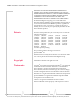
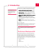
Table Of Contents

CDMA and GSM / UMTS Mini Card Hardware Integration Guide
10 Proprietary and Confidential 2130114
In the event of a discrepancy in values between this guide and the Product Specification Document (PSD), the PSD takes precedence.
ForinstructionsonsettinguptheUDK,seePCIExpressMini
CardDevKitQuickStartGuide(Document2130705).
Required connectors
Note: Contact vendors before
choosing your connectors — the
numbers included here are for
reference only. Choose
connectors that are appropriate
to your design.
Whenintegratingthesemodulesintoyourhostdevice,you
needthefollowingconnectortypes:
• RFcablesthatmatewithHiroseU.FLconnectors(model
U.FL
#CL331‐0471‐0‐10).Modulesincludeoneortwo
connectorjacksdependingonindividualmodulesupport
fordiversityorGPSfunctionality.
• Industry‐standardmatingconnectorfor52‐pinEDGE—
somemanufacturersincludeTyco,Foxconn,andMolex.For
example,theconnectorusedontheMiniCardDevKit
boardisaMolex67910‐0001.
• Industry‐standardUSIMconnector(MC87xxonly)—the
actualconnectoryouusedependsonhowyourdevice
exposestheUSIMsocket.Forexample,theUSIMconnector
usedontheMiniCardDevKitboardisanITTCCM03‐
3518.
Guide organization
Thisguideincludesthefollowingsections:
1. Introduction(thissection)
2. Power Interface(p.15)
Describespowercontrolsignalsusedbythemoduleand
discussesdesignissuesrelatedtopowersupply
integration.
3. RF Integration(p.19)
Describesantennaconnectionmethodsandgroundingissues,
RFinterferenceanddesenseissues.
4. Audio Interface(p.25)
Describessupportedaudiomodesandrelat eddetails.
5. Host / Module Interfaces(p.35)
DescribestheUSBinterfaceforhost/modulecommunication,
andtheUSIMinterfaceforhost/moduleintegration.
6. Regulatory Information(p.37)
Describesregulatoryapprovalsandregulatoryinformation
requirements.
7. Acronyms and Definitions(p.41)
Listsacronymsanddefinitionsusedthroughoutthisguide.
8. Index(p.121)
Note: The term "host" always refers to the host device.