MP 875 Modem User Guide 2130808 Rev 1.
Preface Important Notice Due to the nature of wireless communications, transmission and reception of data can never be guaranteed. Data may be delayed, corrupted (i.e., have errors) or be totally lost.
MP875 Modem User Guide REVENUE OR ANTICIPATED PROFITS OR REVENUE ARISING OUT OF THE USE OR INABILITY TO USE ANY SIERRA WIRELESS PRODUCT, EVEN IF SIERRA WIRELESS AND/OR ITS AFFILIATES HAS BEEN ADVISED OF THE POSSIBILITY OF SUCH DAMAGES OR THEY ARE FORESEEABLE OR FOR CLAIMS BY ANY THIRD PARTY.
Preface Trademarks AirCard® and “Heart of the Wireless Machine®” are registered trademarks of Sierra Wireless. Watcher® is a trademark of Sierra Wireless, registered in the European Community. Sierra Wireless, the Sierra Wireless logo, the red wave design, and the red‐tipped antenna are trademarks of Sierra Wireless. Windows® is a registered trademark of Microsoft Corporation. QUALCOMM® is a registered trademark of QUALCOMM Incorporated. Used under license.
MP875 Modem User Guide Revision History Revision number 1.1 6 Release date August 2007 Changes • Removed detail about AT command parameters, instead directing users to the MP 3G Modems AT Command Reference manual. (document #2130810.) • Updated regulatory information for Canada and the USA. (See “Regulatory Information” on page 77.). 1.2 January 2008 • Added NAT and WAP information. 1.3 February 2008 • Added battery cable information under power connection. 1.
Contents Introducing the MP Modem . . . . . . . . . . . . . . . . . . . . . . . . . . . . . . . . . . . . . . . . . .13 Network connections . . . . . . . . . . . . . . . . . . . . . . . . . . . . . . . . . . . . . . . . . . . . . . 14 Accounts and coverage . . . . . . . . . . . . . . . . . . . . . . . . . . . . . . . . . . . . . . . . . . . . 14 Supported GSM radio frequencies . . . . . . . . . . . . . . . . . . . . . . . . . . . . . . . 15 Connection methods . . . . . . . . . . . . . . . . . . . . . . . .
MP875 Modem User Guide Install the MP modem . . . . . . . . . . . . . . . . . . . . . . . . . . . . . . . . . . . . . . . . . . . . . Step 1 — Mount the MP modem . . . . . . . . . . . . . . . . . . . . . . . . . . . . . . . . . . Select a location for the MP modem . . . . . . . . . . . . . . . . . . . . . . . . . . . Mounting the MP modem . . . . . . . . . . . . . . . . . . . . . . . . . . . . . . . . . . . . Ground the MP modem . . . . . . . . . . . . . . . . . . . . . . . . . . . . . . . . . . . . . .
Contents 3G Watcher software. . . . . . . . . . . . . . . . . . . . . . . . . . . . . . . . . . . . . . . . . . . . . . . 3G Watcher Help . . . . . . . . . . . . . . . . . . . . . . . . . . . . . . . . . . . . . . . . . . . . . . Launching 3G Watcher . . . . . . . . . . . . . . . . . . . . . . . . . . . . . . . . . . . . . . . . . Connection to MP Physical Interface . . . . . . . . . . . . . . . . . . . . . . . . . . . . . Changing the Physical Interface . . . . . . . . . . . . . . . . . . . . . . . . . .
MP875 Modem User Guide I/O device installation and configuration . . . . . . . . . . . . . . . . . . . . . . . . . . . . . Connector pinouts . . . . . . . . . . . . . . . . . . . . . . . . . . . . . . . . . . . . . . . . . . . . . Port specifications . . . . . . . . . . . . . . . . . . . . . . . . . . . . . . . . . . . . . . . . . . Digital input devices . . . . . . . . . . . . . . . . . . . . . . . . . . . . . . . . . . . . . . . . . . . Example: panic button connections . . . . . . . . . . . . . . . . .
Contents I/O port characteristics. . . . . . . . . . . . . . . . . . . . . . . . . . . . . . . . . . . . . . . . . . . . . 75 3G Watcher software. . . . . . . . . . . . . . . . . . . . . . . . . . . . . . . . . . . . . . . . . . . . . . . 76 Wireless access point specifications . . . . . . . . . . . . . . . . . . . . . . . . . . . . . . . . . 76 Regulatory Information . . . . . . . . . . . . . . . . . . . . . . . . . . . . . . . . . . . . . . . . . . . . . .77 Canada . . . . . . . . . . . . . . . . . . . .
MP875 Modem User Guide 12 2130808
1: Introducing the MP Modem • Accounts and coverage • Connection methods • Virtual serial port • VPN support for RNAP • Software • Documentation Note: Do not connect the MP modem to a USB port on a computer before installing the software. (See “Step 5 — Install the software” on page 37.) The Sierra Wireless MP modem provides a wireless network connection for portable computers in vehicles or offices.
MP875 Modem User Guide Network connections The MP modem operates over the following networks, with connectivity and speed dependent on your service provider and account: • High Speed Uplink Packet Access (HSUPA) — up to 2.
Introducing the MP Modem Account provisions Your account may restrict usage of certain networks or may limit your connection time or data transmission.
MP875 Modem User Guide The MP modem VSPs are available on both USB and Ethernet interfaces. For information on enabling a virtual serial port, see the MP 3G Modems AT Command Reference manual (document #2130810). VPN support for RNAP This feature allows for the exchange of Remote Network Access Protocol (RNAP1) data between the MP modem and a remote server accessible only through a Virtual Private Network (VPN) connection. When using this feature, you must have 3G Watcher running on the computer.
Introducing the MP Modem versions of the software and firmware are released, they are posted at www.sierrawireless.com. MP Modem Manager MP Modem Manager is a web‐based diagnostic and management tool that allows you to remotely monitor and configure a fleet of MP modems. With MP Modem Manager you can: • Diagnose and troubleshoot field issues. • Identify MP modem firmware versions and remotely upgrade firmware. • Organize MP modems into groups for table viewing of modem and network status.
MP875 Modem User Guide Online help is provided with 3G Watcher. It describes all the icons and indicators in 3G Watcher and provides detailed instructions on using 3G Watcher to make data connections. When using 3G Watcher, you can access help through the menu system or by pressing the key. The MP 3G Modems AT Command Reference manual (document #2130810) describes the available AT command set.
2: Getting Started • Plan your MP modem installation • Required equipment • System requirements This chapter provides: • An overview of the installation process • Information about the equipment you’ll need • System requirements for the clients you want to use with the MP modem • Planning considerations Overview of installation steps: • Plan the installation. · Location · Connection type · Routing Rev 1.5 Jul.08 • Ensure required equipment is available.
MP875 Modem User Guide Plan your MP modem installation This section guides you through the decisions you need to make before you begin the installation. Where do you want to install your MP modem? The MP modem can be installed in a vehicle or in an office. The same installation steps apply with the following exceptions: • If you are installing the MP modem in a vehicle: · Use the power harness to connect the MP modem to the vehicle battery.
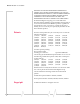
Getting Started The following table summarizes the advantages and disadvan‐ tages of the various interfaces: Serial USB Ethernet WAP a Data connection type Client-initiated MP modem pro-active initiation MP modem pro-active initiation MP modem pro-active initiation Interface hierarchy b Lowest priority Overrides serial Overrides USB and serial Overrides USB and serial. Overrides Ethernet in non-NAT mode. In NAT mode (multi-client mode), Ethernet and WAP are supported simultaneously.
MP875 Modem User Guide Required equipment Package contents Each MP modem box contains: • The MP modem • A mounting template • Mounting screws and washers • An installation and documentation CD • A power harness If any of these are missing, please contact your account manager.
Getting Started • I/O cable (optional). This is required if a panic button, sensor, gauge, or other I/O device is installed. System requirements Before you begin the installation, ensure your computer meets the following system requirements necessary for the instal‐ lation and running of 3G Watcher software: Note: Do not connect the MP modem to a USB port on a computer before installing the software.
MP875 Modem User Guide 24 2130808
3: Hardware and Software Installation • Install the MP modem This chapter provides instructions for installing the MP modem, installing the 3G Watcher software, and activating your account. The MP modem installation should be done by a professional. Before you begin the installation, ensure that you have all the necessary components and equipment listed in “Required equipment” on page 22, and have read the “Installation overview” section below.
MP875 Modem User Guide Connector panel The MP 875 modem has the following connectors: WAP antenna for wireless access point GPS antenna (female SMA) RS-232 serial (female DB9) Serial Host USB Host GPS I/O connector (DB15HD) Ethernet USB (Type B) Ethernet Host AP I/O Power Main RF Main RF antenna (female TNC) Power harness (Molex connector) Figure 3-2: MP 875 modem rear connectors GPS and I/O options The MP modem provides support for GPS (Global Positioning System) and for attaching input/ou
Hardware and Software Installation 4. Connect the cable that runs between the MP modem and your computer to the MP modem. Do not connect the cable to the computer until you have installed the software. 5. Install the software. 6. Start 3G Watcher and activate your account. 7. Test the system. Install the MP modem Step 1 — Mount the MP modem Note: Power off the MP modem, your computer, and any other devices while you are connecting cables.
MP875 Modem User Guide Use the supplied mounting screws and washers to secure the MP modem through the holes along the edge of the case bottom. Figure 3-3: Mounting the MP modem. Arrows indicate the mounting holes. The front cover is open for illustration purposes only. Close it before mounting. Ground the MP modem Note: Electrical installations are potentially dangerous and should be performed by personnel thoroughly trained in safe electrical wiring procedures for vehicles.
Hardware and Software Installation You can also use a ground screw on the connector panel of the MP modem. Use a 16‐gauge wire if you choose to use a ground screw. A ground screw is not required as long as the power harness is properly grounded. I/O Power If you are using a ground screw, insert it here. Figure 3-4: The ground screw connector on the connector panel. Note: Tighten cables connected to the MP modem by hand. Do not use tools.
MP875 Modem User Guide · 2100 MHz · EDGE and GPRS networks: · 850 MHz · 900 MHz · 1800 MHz · 1900 MHz If your MP modem will only be connected to networks that use one of the bands, an appropriate single‐band antenna is sufficient. Contact your service provider for information about radio bands used in your area. • Access point antenna. The 2.4 GHz AP antenna connects to the AP antenna connector on the rear of the MP modem.
Hardware and Software Installation Install the antennas and cables Note: When connecting the cables, hand-tighten the connectors; do not use tools. To install the Main RF, GPS, and AP antennas: Note: To avoid RF interference problems and possible damage to the MP modem, do not power on the MP modem before connecting the Main RF antenna. 1. Mount each antenna according to the instructions provided with it. 2. Thread the antenna cables to the MP modem. Secure the cables as necessary. 3.
MP875 Modem User Guide Note: Electrical installations are potentially dangerous and should be performed by personnel thoroughly trained in safe electrical wiring procedures for vehicles. Power connector Note: Connector part numbers: 39-01-2040 or 39-01-2045. Pins part number: 39-00-0039. The power harness connects to the MP modem with a Molex connector.
Hardware and Software Installation Note: Do not install an on/off switch on the main (red) battery line, or connect the white ignition sense wire to the red battery wire. Both configurations bypass the MP modem's controlled shutdown sequence, and may cause data loss and subsequent power-on problems. Incorrect wiring may also drain the vehicle battery.
MP875 Modem User Guide —or— Note: If you choose to install a separate switch, it must be connected to the white ignition sense wire, not the red battery wire, so that the MP modem can perform a controlled shutdown, as described on page 32. • Separately switched. Connect the white ignition sense wire to a separate switch mounted in a convenient location, which allows the MP modem to be turned on or off regardless of the position of the ignition key.
Hardware and Software Installation Office installation Use the AC/DC adapter available from Sierra Wireless to connect the power harness to a standard outlet. Step 4 — Connect the MP modem to computer cable The MP modem connects to: • A computer through a USB, Ethernet, or serial port • Other optional devices through the DB15HD I/O connector Note: Do not connect the MP modem to the computer until you have installed the software.
MP875 Modem User Guide Serial connector (DB9) pinouts The MP modem is configured as DCE (Data Communications Equipment) and uses the standard RS232 pin designations: DB9 MALE 1 DB9 female connector 5 9 6 1. Data Carrier Detect (DCD) 2. Transmitted Data (TxD)* 3. Received Data (RxD)* 4. Data Terminal Ready (DTR) 5. Signal Ground (GND) 6. Data Set Ready (DSR) 7. Clear To Send (CTS) 8. Request To Send (RTS) 9.
Hardware and Software Installation I/O port connections The MP modem’s I/O port is a standard female DB15HD connector for remote monitoring of gauges, sensors, and alarms. If you are planning to use these devices, you need to create a custom I/O cable. See “Configuring the MP Modem to Report GPS and I/O Data” on page 55. Step 5 — Install the software Note: You must be logged in with administrative privileges to install the software. Follow these steps to install 3G Watcher and the MP modem driver: 1.
MP875 Modem User Guide As well as providing the SIM, your service provider should give you the account information needed to configure the MP modem to use the account: a user name, password, and APN (Access Point Name). Insert the SIM Card The MP modem has a SIM card slot next to the lights on the indicator panel. The slot is protected by a removable rubber cover, and houses a SIM card sled. To insert a SIM card into the MP modem: 1. Open the rubber cover. 2.
Hardware and Software Installation Set up connection profiles Note: Your profiles are stored on your MP modem —not on the SIM card. If you use your SIM card in another device you must create a profile on that device. Unless your MP modem was pre‐configured by your reseller or service provider, you must set up at least one connection profile before you can use it to access the Internet. Some service providers offer a single profile.
MP875 Modem User Guide 5. Complete the following fields: · Profile Name (any meaningful description of the profile, such as the name of your service provider) · User Name · Password, and/or APN, if applicable. (Check with your service provider for specific requirements for the user name and password.) 6.
Hardware and Software Installation locate the .exe file for the software application you want to autolaunch. 8. If you have more than one profile, select Profiles, and in the Default Profile field, choose the default profile from the drop‐down list. (3G Watcher uses this profile for the autoconnect feature. It is also used to establish a connection if you click the Connect button without selecting a profile.) 9. Click OK.
MP875 Modem User Guide 42 2130808
4: MP Modem Operation • Status indicators • 3G Watcher software • Establishing connections Operating the MP modem requires some knowledge of both the MP modem hardware and the 3G Watcher software. This chapter describes the basics of each. Turning the MP modem on and off If the MP modem is installed in a vehicle, the way in which the MP modem is wired determines how it is powered on and off.
MP875 Modem User Guide Status indicators The MP modem’s indicator panel includes four indicator lights. Power indicator Transmit (Tx) Receive (Rx) indicator indicator GPS indicator Figure 4-1: The indicator panel of the MP modem. The following table shows the behavior of the LEDs during normal MP modem operation: Table 4-1: LED operation LED Power 44 Behavior Indicates Off MP modem is not powered. Rapid flashing MP modem is powered and has not acquired network service. Slow flashing (about 1.
MP Modem Operation Reset the MP modem The reset button for the MP modem is on the top of the housing. To reset the MP modem, press the button until all four indicator lights illuminate. (Do not use sharp imple‐ ments that might puncture the rubber.) Resetting the MP modem is equiv‐ alent to turning the MP modem off and on. This terminates any data connection and causes the MP modem to perform a self‐test. (Stored settings are not lost.) Figure 4-2: The MP modem reset button.
MP875 Modem User Guide Launching 3G Watcher To launch 3G Watcher: 1. Ensure that the SIM card is inserted into the card slot (see “Insert the SIM Card” on page 38). 2. Start 3G Watcher by choosing Start > Programs > Sierra Wireless Inc > 3G Watcher > 3G Watcher, or double click the desktop shortcut. Connection to MP Physical Interface 1. Go to Tools > MP Physical Interface Note: MP Physical Interface shows disabled under Tools after the connection is established. 2. Select USB, Ethernet, or Serial.
MP Modem Operation 1. Click on the Disconnect button, if the watcher is connected to your MP. 2. Go to Tools > MP Physical Interface Figure 4-4: Options Menu 3. Select USB, Ethernet, or Serial. 4. Click OK Watcher closes, reopens and re‐initializes itself. 3G Watcher window The main 3G Watcher window includes a number of elements that let you control and monitor your MP modem and your connection to the network.
MP875 Modem User Guide • DUN - Name of your service provider or connection type. Depending on the operating mode and settings in 3G Watcher, a connection may be automatically established when 3G Watcher is launched. Otherwise, you can establish a connection by selecting the connection type and clicking the Connect button. Auto-Connect for DUN Note: DUN connection is not available when WiFi is enabled The MP needs to be connected to the Watcher with serial, for establishing DUN Autoconnect. 1.
5: Configuring the Router Functions • Non-NAT mode • NAT mode • MP modem networking basics in NAT mode • Static IP and TCP/ UDP port forwarding in NAT mode This chapter describes the router functions of the MP modem and shows you how to configure the MP modem to use its router capabilities. The MP modem supports Network Address Translation (NAT).
MP875 Modem User Guide Non-NAT mode In non‐NAT configuration, you can connect only one client device, such as a computer to the MP modem, as shown in Figure 5‐1. In this mode, the IP address obtained from the external network is passed directly to the client device, which is why there can be only one client. External Network Serial, USB, Ethernet, or WAP interface Client device IP:aaa.bbb.ccc.ddd MP modem in non-NAT mode IP:aaa.bbb.ccc.
Configuring the Router Functions Local network External network WAP network 192.168.2.1 205.205.30.12 PC client 1 192.168.2.19 Ethernet 192.168.1.1 MP modem PC client 2 192.168.2.18 PC client 3 192.168.1.19 PC client 4 192.168.1.18 MP modem networking basics in NAT mode In NAT mode, the MP modem has a built‐in DHCP server that automatically assigns private network IP addresses to devices connected to it. The IP addresses assigned are in the range 192.168.1.10 to 192.168.1.19 for Ethernet and 192.
Configuring the Router Functions Enable the router The router features are enabled when NAT is enabled. By default, NAT is disabled. To enable NAT: 1. In Watcher, select Tools > Options > MP. 2. Under Network Settings, select Network Address Trans‐ lation (NAT) and from the drop‐down list select Enabled. The MP modem automatically resets in order for the change to take effect.
Configuring the Router Functions 2. In Watcher, select Tools > AT Commands, and use the AT!MPSTATICROUTE command to set up static routing. For more information, see the 3G MP Modems AT Command Reference manual (document #2130810). 3. Reset the modem. Select Tools > AT Commands, and use the AT!MPGRESET command to reset the MP modem. 4. Click OK.
MP875 Modem User Guide 54 2130808
6: Configuring the MP Modem to Report GPS and I/O Data • I/O device installation and configuration The MP modem is capable of reporting position and heading information using the embedded GPS module, as well as the status of sensors, gauges, and alarms connected to the I/O (Input/Output) port. The MP modem is typically installed in a fleet of vehicles with the GPS and/or I/O data being sent to a central office or dispatch for processing.
MP875 Modem User Guide GPS protocols and commands Note: The “MP 3G Modems TAIP Reference manual” (document #2130312) provides a description of the TAIP commands that can be used with the MP modem. This is available at www.sierrawireless.com. Information about Trimble GPS modules, including more documentation on TAIP commands, is available at www.trimble.com. More information on NMEA message standards is available at www.nmea.org.
Configuring the MP Modem to Report GPS and I/O Data GPS TAIP quick reference The following table is a quick summary of the TAIP message identifiers. For detailed information and message syntax, see the MP 3G Modems TAIP Reference manual (document #2130312) and the GPS documentation on TAIP commands available at www.trimble.com.
MP875 Modem User Guide Before using the digital input/output lines, you must configure them as inputs or outputs. Connector pinouts The MP modem’s I/O port is a female DB15HD connector with eight active I/O pins: • Two (2) digital I/O pins. • Two (2) digital input pins. • Four (4) analog input pins. There are also six reserved pins and one ground pin. 1 6 11 5 10 15 DB15HD male cable DB15HD female connector on rear of MP modem 1. Reserved—do not connect 2. Reserved—do not connect 3.
Configuring the MP Modem to Report GPS and I/O Data A digital input can be connected to four of the pins on the DB15HD connector: Pins 3, 4, 11, and 12. (Pins 3 and 11 could alternatively be used for digital output.) Note: Before using the input/output lines, you must configure them as inputs or outputs. Typically a digital input device should be connected between Ground (Pin 10) and the input port (Pin 3, 4, 11, or 12). Figure 6-2: A button wired to Pin 4 (digital input) and Pin 10 (Ground).
MP875 Modem User Guide Digital output devices Digital output devices are those that have only two states and the state is controlled by a signal from the MP modem. Any device that is to be switched on and off from 3G Watcher would be installed as a digital output device. A digital output can be connected to two of the pins on the DB15HD connector: Pins 3 and 11. (These can be used for either input or output.) Note: Before using the input/output lines, you must configure them as inputs or outputs.
Configuring the MP Modem to Report GPS and I/O Data ~ Typically an analog input device should be connected between Ground (pin 10) and the input port (Pin 7, 8, 14, or 15). Figure 6-4: A sensor wired to Pin 7 (analog input) and Pin 10 (Ground). The analog input ports use a 10‐bit (1024‐step) analog‐to‐ digital converter over a range from 0 to 3.45 VDC, yielding a digital step resolution of 0.0032 V.
MP875 Modem User Guide Analog input setup The Analog Input window (Tools > Options > MP > Input/Output) is used to configure devices on the four analog inputs. Each tab corresponds to a pin: Analog Tab Connector Pin Input 1 14 Input 2 7 Input 3 15 Input 4 8 To configure an analog sensor or gauge, select the tab that corresponds to the pin you are using and complete the fields as follows: • Label: Enter a description of the sensor or gauge (Measured Voltage, Vehicle Speed, etc.
Configuring the MP Modem to Report GPS and I/O Data Digital I/O setup The Digital Input/Output window (Tools > Options > MP > Input/Output > Digital I/O) is used to configure devices on the two digital I/O and two digital input ports.
MP875 Modem User Guide 64 2130808
7: Sending Data to Your Network Application • Retrieve the Unique Mobile Device ID This chapter discusses how to configure the MP modem to send GPS and I/O data to a network server. This is a simple process, but if there are any firewalls on your network or your service provider’s network, the data must be routed through or around the firewall. A general discussion of some methods of dealing with firewalls is provided.
MP875 Modem User Guide The fast rate timer only becomes active when an alarm condition is triggered by a rise or drop in the level of one of the digital I/O channels. The default for the fast rate timer is three seconds. Note: When the fast rate timer is set to 0, a single report is sent when an I/O alarm is triggered. If the GPS timer is set to a value other than 0, it controls the frequency of reports in the absence of any alarm or event triggers.
Sending Data to Your Network Application Note: The “MP 3G Modems TAIP Reference manual” (document #2130312) provides a description of the TAIP commands you can use. This is available at www.sierrawireless.com. Information about GPS modules, including more documentation on TAIP commands, is available at www.trimble.com. If the GPS timer is set to 0, the reporting interval is determined by the configuration of the GPS module.
MP875 Modem User Guide Note: More information on NMEA message standards is available at www.nmea.org. If the module is configured for NMEA, data is sent at five‐ second intervals. (The interval cannot be changed when the module is configured for NMEA because NMEA is strictly a reporting protocol.) Monitoring and Tracking configuration You can use 3G Watcher to configure the MP modem to send MTP data to a network server: 1.
Sending Data to Your Network Application The problem created by Network Address Translation Note: A similar problem may occur if NAT is in use on your network. The host application may reside on a server that has a private IP address. You must configure the MP modem to send data to a server on your network with a public IP address, and configure the server to recognize the MTP data and route it appropriately.
MP875 Modem User Guide Note: NetMotion Wireless, Inc. develops client-server applications that attempt to overcome the issues caused by NAT addressing by assigning its own consistent private IP addresses. This software offers a potential solution to NAT issues, but it is untested by Sierra Wireless, and Sierra Wireless does not provide support for it. Solutions to the NAT problem If your service provider is using NAT, it is best to work with the provider in devising a solution.
8: Support and Warranty Technical support To obtain technical support for your MP modem, and firmware and software upgrades, please contact your account manager. Online technical support resources are also available at www.sierrawireless.com. Warranty Sierra Wireless, Inc. warrants the MP modem against all defects in materials and workmanship for a period of three (3) years from the date of purchase. The sole responsibility of Sierra Wireless, Inc.
MP875 Modem User Guide 72 2130808
9: Technical Specifications This chapter provides technical data for the MP 875W modem. Note: The technical specifications are subject to change without notice. Regulatory, radio frequency and electrical specifications Approvals FCC Industry Canada PTCRB EU RoHS Network compliance GSM GPRS EDGE: (Class 12), peak 236 kbps downlink UMTS: peak 384 kbps uplink/downlink HSUPA: (Cat 4), peak 2.
MP875 Modem User Guide Environmental specifications Operating temperature -30°C to +70°C (-22°F to +158°F) Storage temperature -40°C to +85°C (-40°F to +185°F) Humidity 95% RH non-condensing MIL 202G, Sections 103B and 106G Rain / splash MIL 810F, Section 506.4, Procedure III SAE KJ1455, Section 4.4 Drop MIL 810F, Section 516.5 SAE J1455, Section 4.10.3.1 Shock MIL 202G, Section 213B MIL 810F, Section 516.5 SAE J1455, Sections 4.10.3.2 and 4.10.3.
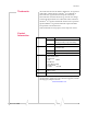
Technical Specifications Host interfaces Serial One — DB9 female USB One — USB Type B, USB 1.1/2.0 compliant Ethernet One — RJ45 female Other interfaces Input / output One — High-density DB15 female Network antenna One — TNC female GPS antenna One — SMA female Reset One — Manual reset button Power One — Molex 39-01-0029 female AP antenna One — SMA female GPS specifications Satellite channels 12 channel, continuous tracking Protocols TSIP, TAIP, NMEA 0183 V3.
MP875 Modem User Guide Digital inputs Open collector, max current 500 mA Vih, min 2 VDC Vil, max 0.8 VDC Vih, max 36 VDC Digital outputs Open collector Analog input count Total: 4 Analog input Zero-scale: 0 VDC Full-scale: 3.
10: Regulatory Information • European Union Note: Unauthorized modifications or changes not expressly approved by Sierra Wireless, Inc. could void compliance with regulatory rules, and thereby your authority to use this equipment. Canada To ensure that the MP modem meets Health Canada’s Safety Code 6 requirements, a separation distance of at least 20 cm (8 inches) must be maintained between the modem’s antenna and the body of the user and any nearby persons at all times and in all applications and uses.
MP875 Modem User Guide Note: This equipment has been tested and found to comply with the limits for a Class A digital device, pursuant to Part 15 of the FCC Rules. These limits are designed to provide reasonable protection against harmful interference when the equipment is operated in a commercial environment.
Index Numerics 3G Watcher, 45– 48 A digital input configuration, 63 wiring, 58 digital output configuration, 63 wiring, 60 dimensions, 74 documentation, 17 account, 37 alert rate timer, 65 analog input configuration, 62 wiring, 60 analog sensor, 61 antenna, 29 antenna connector, 26 AP antenna, 77 approvals, 73 AT commands I/O configuration, 61 MTP configuration, 65 port mapping, 52 port routing, 53 reset modem, 52, 53 static IP addressing, 52 static routing, 52, 53 unique mobile device ID, 70 unlock the
MP875 Modem User Guide inputs. See I/O devices interfaces, 75 L launch browser automatically on high‐speed connection, 40 VPN automatically on high‐speed connection, 40 LEDs, 44 low rate timer, 65 M manuals, 17 mode NAT, 50, 51 non‐NAT, 50 mounting, 27– 28 MTP configuring, 65 report frequency, 65 N NAT, 49, 69 NAT mode, 50, 51 Network Address Translation. See NAT. NMEA, 56 non‐NAT mode, 50 O on/off switch, 32 output power, 73 outputs. See I/O devices.
Index Watcher, 45– 48 weight, 74 Rev 1.5 Jul.
MP875 Modem User Guide 82 2130808