
Modem User Manual


MP875 Modem User Guide
26 2130808
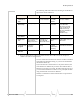
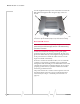
Connector panel
TheMP875modemhasthefollowingconnectors:
Figure 3-2: MP 875 modem rear connectors
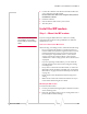
GPS and I/O options
TheMPmodemprovidessupportforGPS(GlobalPositioning
System)andforattachinginput/outputdevices.
GPS.IfyouplantousetheMPmodem’sbuilt‐inGPSmodule,
youmustconnectaGPSantennausinganantennacable,or
useacombinationantennathatcanconnecttoboththeGPS
andMainRFconnectorsontheMPmodemhousing.
OtherI/Odevices.Otherdevices,suchaspanicbuttons,
sensors,orgaugesmayalsobeinstalledwiththeMPmodem
andconnectedwithanI/OcabletotheI/Oport.(
See“I/Oport
connections”onpage37.)
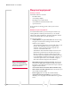
Overview of installation steps
Note: Electrical installations are
potentially dangerous and
should be performed by
personnel thoroughly trained in
safe electrical wiring procedures
for vehicles.
TheinstallationprocessfortheMPmodemvariesdepending
onhowyouplantouseit,whereitbestfits,andwhichofits
featuresyouplantouse.Themainstepsare:
1. MounttheMPmodem.
2. Mounttheantennasandconnectthecables.
· MainRFantennaandcable
· GPSantennaandcable,ifyouplantouseGPS
· WAPantennaandcable(MP595Wonly)
3. Connectthepowerharness.
I/O connector (DB15HD)
RS-232 serial (female DB9)
USB (Type B)
Ethernet
Power harness (Molex connector)
Main RF antenna (female TNC)
Serial Host
USB Host
GPS
Ethernet Host
I/O
Main RF
Power
AP
WAP antenna for wireless
access point
GPS antenna
(female SMA)