MP 875 Modem User Guide 2130808 Rev 1.
Preface Important Notice Due to the nature of wireless communications, transmission and reception of data can never be guaranteed. Data may be delayed, corrupted (i.e., have errors) or be totally lost.
MP 875 Modem User Guide REVENUE OR ANTICIPATED PROFITS OR REVENUE ARISING OUT OF THE USE OR INABILITY TO USE ANY SIERRA WIRELESS PRODUCT, EVEN IF SIERRA WIRELESS AND/OR ITS AFFILIATES HAS BEEN ADVISED OF THE POSSIBILITY OF SUCH DAMAGES OR THEY ARE FORESEEABLE OR FOR CLAIMS BY ANY THIRD PARTY.
Preface Trademarks AirCard® and “Heart of the Wireless Machine®” are registered trademarks of Sierra Wireless. Watcher® is a trademark of Sierra Wireless, registered in the European Community. Sierra Wireless, the Sierra Wireless logo, the red wave design, and the red-tipped antenna are trademarks of Sierra Wireless. Windows® is a registered trademark of Microsoft Corporation. QUALCOMM® is a registered trademark of QUALCOMM Incorporated. Used under license.
MP 875 Modem User Guide 6 2130808
Contents Introducing the MP 875 Modem . . . . . . . . . . . . . . . . . . . . . . . . . . . . . . . . . . . . . .11 Network connections . . . . . . . . . . . . . . . . . . . . . . . . . . . . . . . . . . . . . . . . . . . . . . 12 Accounts and coverage . . . . . . . . . . . . . . . . . . . . . . . . . . . . . . . . . . . . . . . . . . . . 13 Supported GSM radio frequencies . . . . . . . . . . . . . . . . . . . . . . . . . . . . . . . 14 USB, Ethernet, or serial computer connection . . . . . . . . . . . . .
MP 875 Modem User Guide Reading the status indicators . . . . . . . . . . . . . . . . . . . . . . . . . . . . . . . . . . . . . . . 38 Resetting the MP modem . . . . . . . . . . . . . . . . . . . . . . . . . . . . . . . . . . . . . . . 39 3G Watcher software . . . . . . . . . . . . . . . . . . . . . . . . . . . . . . . . . . . . . . . . . . . . . . 3G Watcher Help . . . . . . . . . . . . . . . . . . . . . . . . . . . . . . . . . . . . . . . . . . . . . . Launching 3G Watcher . . . . . . . . . . . . . . . .
Contents Technical Specifications . . . . . . . . . . . . . . . . . . . . . . . . . . . . . . . . . . . . . . . . . . . .59 Regulatory, radio frequency and electrical specifications . . . . . . . . . . . . . . . 59 Environmental specifications . . . . . . . . . . . . . . . . . . . . . . . . . . . . . . . . . . . . . . . 60 Weight and dimensions . . . . . . . . . . . . . . . . . . . . . . . . . . . . . . . . . . . . . . . . . . . . 60 Host interfaces . . . . . . . . . . . . . . . . . . . . . . . . . . . . .
MP 875 Modem User Guide 10 2130808
1: Introducing the MP 875 Modem 1 • Network connections • Accounts and coverage • USB, Ethernet, or serial computer connection • USB, Ethernet, or serial computer connection • Virtual serial port • VPN support for RNAP • Software • Documentation Note: Do not connect the MP modem to a USB port on a computer before installing the software. (See “Step 5—Install the software” on page 31.) The Sierra Wireless MP modem provides a wireless network connection for portable computers installed in vehicles.
MP 875 Modem User Guide The following diagram illustrates how the system works: GPS satellite Antenna MP Modem MP modem installed in vehicle with a notebook computer Base station Network VPN over Internet Computer/Host Firewall and Router Network operations center Private / dedicated link Host Customer fixed end system Figure 1-1: The MP modem and the network.
Introducing the MP 875 Modem • Universal Mobile Telecommunications System (UMTS)— up to 384 kilobits per second (kbps). • Enhanced Data GSM Environment (EDGE)—up to 236 kbps. • General Packet Radio Service (GPRS)—up to 56 kbps. • Circuit switched (dial-up) data connections. Once a connection is established, you can open your browser and connect to web sites and access other Internet services such as e-mail.
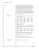
MP 875 Modem User Guide Supported GSM radio frequencies The MP 875 modem has tri-band capability on HSDPA and UMTS networks, operating on: • 850 MHz • 1900 MHz • 2100 MHz and quad-band capability on EDGE and GPRS, operating on: • 850 MHz • 900 MHz • 1800 MHz • 1900 MHz USB, Ethernet, or serial computer connection You can connect the MP modem to a USB, Ethernet (RJ45), or serial (DB9) port on a computer. When connected to a USB or Ethernet port, the MP modem behaves like a network card.
Introducing the MP 875 Modem VPN support for RNAP This feature allows for the exchange of Remote Network Access Protocol (RNAP1) data between the MP modem and a remote server accessible only through a Virtual Private Network (VPN) connection. When using this feature, you must have 3G Watcher running on the computer. The MP modem sends RNAP data over Ethernet or USB to 3G Watcher on the computer.
MP 875 Modem User Guide MP Modem Manager MP Modem Manager is a web-based diagnostic and management tool that allows you to remotely monitor and configure a fleet of MP modems. With MP Modem Manager you can: • Diagnose and troubleshoot field issues. • Identify MP modem firmware versions and remotely upgrade firmware. • Organize MP modems into groups for table viewing of modem and network status. • Configure GPS settings. MP Modem Manager software is available free of charge.
Introducing the MP 875 Modem The MP Modem Manager User Guide (document #2130554) provides information on how to install, configure, and use the MP Modem Manager software to manage a fleet of modems. The Monitoring and Tracking Protocol Guide describes the protocols used in data transmissions between the MP modem and the network server. It provides the information necessary to develop host applications that process GPS and digital input from a fleet of MP modems.
MP 875 Modem User Guide 18 2130808
2: Hardware and Software Installation • Installation overview • Install the MP modem 2 This chapter shows you how to install the MP modem in a vehicle, how to install the 3G Watcher software, and how to activate your account. Before you begin the installation, ensure that you have all the necessary components and equipment listed in the following sections, and have read the “Installation overview” on page 21.
MP 875 Modem User Guide Note: If GPS is being imple mented, you require either two antennas or a combination RF and GPS antenna. • Radio frequency (RF) antenna and cable. The antenna must have the appropriate regulatory approval, 50 ohm impedance, and a male TNC connector. It may be a hard or magnetic-mounted antenna. • GPS antenna and cable (optional). This is necessary if you use the built-in GPS module. • Power supply. This is usually the vehicle’s battery. • Appropriate electrical grounding.
Hardware and Software Installation Installation overview The following diagram illustrates the overall installation. RF/GPS antenna MP modem Note: The MP modem is designed for negative-ground vehicles only. It will not function in a positive-ground vehicle. Figure 2-1: Installation of the MP modem in a vehicle equipped with a notebook computer and a combination antenna, using the car battery for power and ignition-sense wiring for power on/off.
MP 875 Modem User Guide GPS and I/O options The MP modem provides support for GPS (Global Positioning System) and for attaching input/output devices. GPS. If you plan to use the MP modem’s built-in GPS module, you must connect a GPS antenna using an antenna cable, or use a combination antenna that can connect to both the GPS and RF connectors on the MP modem housing. Other I/O devices.
Hardware and Software Installation from the engine compartment, heaters, or the exhaust system, and extreme cold from direct contact with air conditioners or other cooling systems. Never immerse it in any liquid. • If you are replacing a MP modem, you can mount the new MP modem in the same location using the existing mounting holes. • Every device connected to the MP modem, as well as the MP modem itself, should be grounded.
MP 875 Modem User Guide Ground the MP modem Note: Electrical installations are potentially dangerous and should be performed by personnel thoroughly trained in safe electrical wiring procedures for vehicles. Automotive installations usually provide a good quality ground for each piece of electrical equipment. In most cases, ground the MP modem by connecting the black ground wire of the power harness to either the vehicle chassis or to the negative terminal of the battery.
Hardware and Software Installation The built-in GPS module requires a dedicated GPS antenna or a combination antenna with cables to both the RF and GPS antenna connectors on the MP modem. If you already have an MP Modem Combo GPS antenna, you can re-use it with your new MP modem. This antenna has two leads—one for RF (TNC connector) and one for GPS (SMA connector). RF antennas Use an approved RF antenna to connect to the wireless network.
MP 875 Modem User Guide • Ensure that the RF antenna is mounted at least 20 cm (8 inches) from vehicle occupants and bystanders. • Ensure that all radio antennas (RF, GPS, CB radio, car radio) are mounted at least 30 cm (12 inches) or more apart. Install the antennas and cables Note: When connecting the cables, hand-tighten the connectors; do not use tools.
Hardware and Software Installation Power connector Note: Connector part numbers: 39-01-2040 or 39-01-2045. Pins part number: 39-00-0039. The power harness connects to the MP modem with a Molex connector. Power connector (Molex) pinouts The pinouts for the Molex connector on the power harness are: White wire (Ignition sense) Unused Red wire (Battery) Black wire (Ground) Figure 2-6: Pinouts for the power harness. The battery (red) and ignition sense (white) wires in the power harness include 5 A fuses.
MP 875 Modem User Guide • When the ignition sense line is pulled low (less than 2 V), the MP modem performs a controlled shutdown sequence (under software control), de-registering and saving any relevant operational data before powering off. Ignition sense options There are three ways to connect the ignition sense wiring: • Engine on only.
Hardware and Software Installation Power connections Connecting the MP modem’s power wires properly is important—poor connections can damage the wiring, the MP modem, or the vehicle’s electrical system, and can be dangerous. Note: Ensure that all wires are correctly spliced or crimped. Improper grounding and wire connections may lead to equipment damage or safety hazards. Correct wire splicing You can splice the wires of the power harness to the car wiring.
MP 875 Modem User Guide You can connect the MP modem Ethernet port directly to a computer or other Ethernet device with either a cross-over or a straight-through cable. Note: 5-m part number: 6000083. • A serial cable (with a DB9 connector on the MP modem end). The maximum length of the serial cable is 5.5-m (18 feet). Sierra Wireless sells suitable serial cables in 5-m (16-feet) lengths.
Hardware and Software Installation Install the USB, Ethernet or serial cable Note: Ensure that the MP modem and your computer are powered off while installing cables. To install the USB, Ethernet, or serial cable, thread the cable through the vehicle and attach it to the USB, Ethernet, or serial connector on the MP modem. Note: Do not connect the cables to the computer until you have installed the software.
MP 875 Modem User Guide Step 6—Configure your account The MP 875 modem uses a SIM card that stores your account information. You need an account with a service provider for each MP 875 modem you deploy. You should also obtain a SIM card for each account. The SIM contains account infor mation used by the network to identify subscribers and provide access to the appropriate messages and services. The SIM must be inserted in the MP modem’s SIM slot (as described in the next section.
Hardware and Software Installation 5. Insert the sled back into the SIM slot. 6. Push the sled in until it clicks into place in the slot. 7. Close the rubber cover again by fitting in the left edge and then pressing in to seal the cover. Setting up connection profiles Note: Your profiles are stored on your MP 875 modem —not on the SIM card. If you use your SIM card in another device you must create a profile on that device.
MP 875 Modem User Guide 5. Complete the following fields: · Profile Name (any meaningful description of the profile, such as the name of your service provider) · User Name · Password, and/or APN, if applicable. (Check with your service provider for specific requirements for the user name and password.) 6.
Hardware and Software Installation locate the .exe file for the software application you want to autolaunch. 8. If you have more than one profile, select Profiles, and in the Default Profile field, choose the default profile from the drop-down list. (3G Watcher uses this profile for the autoconnect feature. It is also used to establish a connection if you click the Connect button without selecting a profile.) 9. Click OK.
MP 875 Modem User Guide 36 2130808
3: Operating the MP Modem • Reading the status indicators • 3G Watcher software • Establishing connections 3 Operating the MP modem requires some knowledge of both the MP modem hardware and the 3G Watcher software. This chapter describes the basics of each. Turning the MP modem on and off The way in which the MP modem is wired determines how it is powered on and off.
MP 875 Modem User Guide Reading the status indicators The MP modem’s indicator panel includes four indicator lights Power indicator Transmit (Tx) Receive (Rx) indicator indicator GPS indicator Figure 3-1: The indicator panel of the MP 875 modem. The following table shows the behavior of the LEDs during normal MP modem operation: Table 3-1: LED operation LED Power 38 Behavior Indicates Off MP modem is not powered. Rapid flashing MP modem is powered and has not acquired network service.
Operating the MP Modem Resetting the MP modem The reset button for the MP modem is on the top of the housing. To reset the MP modem, press the button until all four indicator lights illuminate. (Do not use sharp implements that might puncture the rubber.) Resetting the MP modem is equiv alent to turning the MP modem off and on. This terminates any data connection and causes the MP modem to perform a self-test. (Stored settings are not lost.) Figure 3-2: The MP modem reset button.
MP 875 Modem User Guide Launching 3G Watcher To launch 3G Watcher: 1. Ensure that the SIM card is inserted into the card slot (see “Inserting the SIM Card” on page 32). 2. Start 3G Watcher by choosing Start > Programs > Sierra Wireless Inc > 3G Watcher > 3G Watcher, or double click the desktop shortcut. 3G Watcher window The main 3G Watcher window includes a number of elements that let you control and monitor your MP modem and your connection to the network.
4: Configuring the MP Modem to Report GPS and I/O Data • GPS configuration and reporting • I/O device installation and configuration 4 The MP modem is capable of reporting position and heading information using the embedded GPS module, as well as the status of sensors, gauges, and alarms connected to the I/O (Input/Output) port. The MP modem is typically installed in a fleet of vehicles with the GPS and/or I/O data being sent to a central office or dispatch for processing.
MP 875 Modem User Guide GPS protocols and commands Note: The “MP 3G Modems TAIP Reference” (document #2130312) provides a description of the TAIP commands that can be used with the MP modem. This is available at www.sierrawireless.com. Information about Trimble GPS modules, including more documentation on TAIP commands, is available at www.trimble.com. More information on NMEA message standards is available at www.nmea.org.
Configuring the MP Modem to Report GPS and I/O Data GPS TAIP quick reference The following table is a quick summary of the TAIP message identifiers. For detailed information and message syntax, see the MP 3G Modems TAIP Reference (document #2130312) and the GPS documentation on TAIP commands available at www.trimble.com.
MP 875 Modem User Guide Before using the digital input/output lines, you must configure them as inputs or outputs. Connector pinouts The MP modem’s I/O port is a female DB15HD connector with eight active I/O pins: • Two (2) digital I/O pins. • Two (2) digital input pins. • Four (4) analog input pins. There are also six reserved pins and one ground pin. 1 6 11 5 10 15 DB15HD male cable DB15HD female connector on rear of MP modem 1. Reserved—do not connect 2. Reserved—do not connect 3.
Configuring the MP Modem to Report GPS and I/O Data A digital input can be connected to four of the pins on the DB15HD connector: Pins 3, 4, 11, and 12. (Pins 3 and 11 could alternatively be used for digital output.) Note: Before using the input/output lines, you must configure them as inputs or outputs. Typically a digital input device should be connected between Ground (Pin 10) and the input port (Pin 3, 4, 11, or 12). Figure 4-2: A button wired to Pin 4 (digital input) and Pin 10 (Ground).
MP 875 Modem User Guide A digital output can be connected to two of the pins on the DB15HD connector: Pins 3 and 11. (These can be used for either input or output.) Note: Before using the input/output lines, you must configure them as inputs or outputs. Typically a digital output device should be connected between Ground (pin 10) and the output port (Pin 3 or 11). Figure 4-3: Wiring for using Pin 3 (digital output) as an electronic switch. Pin 10 is Ground.
Configuring the MP Modem to Report GPS and I/O Data ~ Typically an analog input device should be connected between Ground (pin 10) and the input port (Pin 7, 8, 14, or 15). Figure 4-4: A sensor wired to Pin 7 (analog input) and Pin 10 (Ground). The analog input ports use a 10-bit (1024-step) analog-to digital converter over a range from 0 to 3.45 VDC, yielding a digital step resolution of 0.0032 V.
MP 875 Modem User Guide Analog input setup The Analog Input window (Tools > Options > MP > Input/Output) is used to configure devices on the four analog inputs. Each tab corresponds to a pin: Analog Tab Connector Pin Input 1 14 Input 2 7 Input 3 15 Input 4 8 To configure an analog sensor or gauge, select the tab that corresponds to the pin you are using and complete the fields as follows: • Label: Enter a description of the sensor or gauge (Measured Voltage, Vehicle Speed, etc.
Configuring the MP Modem to Report GPS and I/O Data Digital I/O setup The Digital Input/Output window (Tools > Options > MP > Input/Output > Digital I/O) is used to configure devices on the two digital I/O and two digital input ports.
MP 875 Modem User Guide 50 2130808
5: Sending Data to Your Network Application • Configuring the MP modem to route data to a server • Retrieving the Unique Mobile Device ID 5 This chapter discusses how to configure the MP modem to send GPS and I/O data to a network server. This is a simple process, but if there are any firewalls on your or your service provider’s network, the data must be routed through or around the firewall. A general discussion of some methods of dealing with firewalls is provided.
MP 875 Modem User Guide The low rate timer sets the interval at which reports are sent in the absence of any other trigger or timer. It is in minutes with a default of five minutes. The fast rate timer only becomes active when an alarm condition is triggered by a rise or drop in the level of one of the digital I/O channels. The default for the fast rate timer is three seconds. Note: When the fast rate timer is set to 0, a single report is sent when an I/O alarm is triggered.
Sending Data to Your Network Application Note: The “MP 3G Modems TAIP Reference” (document #2130312) provides a description of the TAIP commands you can use. This is available at www.sierrawireless.com. Information about GPS modules, including more documentation on TAIP commands, is available at www.trimble.com. If the GPS timer is set to 0, the reporting interval is determined by the configuration of the GPS module. If the module is configured for TAIP, you can issue TAIP commands to change the interval.
MP 875 Modem User Guide Note: More information on NMEA message standards is available at www.nmea.org. If the module is configured for NMEA, data is sent at fivesecond intervals. (The interval cannot be changed when the module is configured for NMEA because NMEA is strictly a reporting protocol.) Monitoring and Tracking configuration You can use 3G Watcher to configure the MP modem to send MTP data to a network server: 1.
Sending Data to Your Network Application The problem created by Network Address Translation Note: A similar problem may occur if NAT is in use on your network. The host application may reside on a server that has a private IP address. You must configure the MP modem to send data to a server on your network with a public IP address, and configure the server to recognize the MTP data and route it appropriately.
MP 875 Modem User Guide Note: NetMotion Wireless, Inc. develops client-server applications that attempt to overcome the issues caused by NAT addressing by assigning its own consistent private IP addresses. This software offers a potential solution to NAT issues, but it is untested by Sierra Wireless, and Sierra Wireless does not provide support for it. Solutions to the NAT problem If your service provider is using NAT, it is best to work with the provider in devising a solution.
6: Support and Warranty • Technical support • Warranty 6 Technical support To obtain technical support for your MP modem, and firmware and software upgrades, please contact your account manager. Online technical support resources are also available at www.sierrawireless.com. Warranty Sierra Wireless, Inc. warrants the MP modem against all defects in materials and workmanship for a period of three (3) years from the date of purchase. The sole responsibility of Sierra Wireless, Inc.
MP 875 Modem User Guide 58 2130808
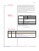
7: Technical Specifications 7 This chapter provides technical data for the MP 875 modem. Note: The technical specifications are subject to change without notice. Regulatory, radio frequency and electrical specifications Approvals FCC Industry Canada PTCRB EU RoHS Network compliance GSM GPRS EDGE: (Class 12), peak 236 kbps downlink UMTS: peak 384 kbps uplink/downlink HSDPA: (Cat 5/6), peak 3.
MP 875 Modem User Guide Environmental specifications Operating temperature -30°C to +70°C (-22°F to +158°F) Storage temperature -40°C to +85°C (-40°F to +185°F) Humidity 95% RH non-condensing MIL 202G, Sections 103B and 106G Rain / splash MIL 810F, Section 506.4, Procedure III SAE KJ1455, Section 4.4 Drop MIL 810F, Section 516.5 SAE J1455, Section 4.10.3.1 Shock MIL 202G, Section 213B MIL 810F, Section 516.5 SAE J1455, Sections 4.10.3.2 and 4.10.3.
Technical Specifications Host interfaces Serial One — DB9 female USB One — USB Type B, USB 1.1/2.0 compliant Ethernet One — RJ45 female Other interfaces Input / output One — High-density DB15 female Network antenna One — TNC female Receive diversity antenna One — SMA female GPS antenna One — SMA female Reset One — Manual reset button Power One — Molex 39-01-0029 female GPS specifications Rev 1.1 Aug.
MP 875 Modem User Guide I/O port characteristics Absolute maximum voltage -0.3 VDC to 36 VDC Digital I/O count Total: 4; two dedicated inputs, two configurable input/outputs Digital inputs Open collector, max current 500 mA Vih, min 2 VDC Vil, max 0.8 VDC Vih, max 36 VDC Digital outputs Open collector Analog input count Total: 4 Analog input Zero-scale: 0 VDC Full-scale: 3.
8: Regulatory Information • Canada • U.S.A. Note: Unauthorized modifica tions or changes not expressly approved by Sierra Wireless, Inc. could void compliance with regulatory rules, and thereby your authority to use this equipment.
MP 875 Modem User Guide 64 2130808
Index Numerics dimensions, 60 documentation, 16 3G Watcher, 39– 40 A account, 32 alert rate timer, 51 analog input configuration, 48 wiring, 46 analog sensor, 47 antenna, 24 antenna connector, 21 approvals, 59 AT commands I/O configuration, 47 MTP configuration, 51 unique mobile device ID, 56 audio connector, 21 autolaunch application on high-speed connection, 34 browser on high-speed connection, 34 VPN on high-speed connection, 34 B browser, launch automatically on high-speed connec tion, 34 C connec
MP 875 Modem User Guide L S launch browser automatically on high-speed connection, 34 VPN automatically on high-speed connection, 34 LEDs, 38 low rate timer, 51 sensors.