
User guide


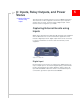


Inputs, Relay Outputs, and Power Status
Rev 2.0 Mar.10 27
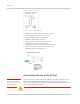
Figure 5-4: Power Connector Diagram
Caution:
Never apply voltage to the Digital inputs. The inputs can only be switched open
or closed to ground.
Monitoring the Input and Output
You can monitor the status of the digital inputs using ACEmanager, AT
Commands, or with special reports sent by email, SMS, or other report types
using Event Reporting. In ACEmanager, select the I/O group.
Digital Input Digital Input/Output
Input Specs(Over temp)
Pin 3 Pin 4
Function Input Output Only
Max VDC 3.3V 3.3V
V Positive VDC 1.3 to 2.2VDC 1.3 to 2.2VDC
V negative VDC 0.6 to 1.2 VDC 0.6 TO 1.5VDC
Hysteresis VDC 0.4 to 1.2VDC 0.4 to 1.2VDC
Internal Pullup 52kohm to 3.3VDC (no pull on pin 4)
Output Specs (Over temp)
Function Input Only Output
IOUT ±50mA
VOHmin (IOH - 16 mA) 2.4V
VOHmin (IOH - 24 mA) 2.3V
VOLmax(IOL 24mA) 0.55V