
User manual

GHI Electronics,LLC Embedded Master User Manual
Embedded Master Products
2.1.7 CAN
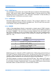
The development system wires one of the available CAN channels (channel 1) to a high
speed transceiver. The outputs CAN_High and CAN_Low are connected to pins 7 and 2
respectively on connector X5. Pins 3 and 6 are connected to ground.
High speed CAN transceivers require termination on the very last endings of the twisted
pair wires. 120 ohm resistor should be on every end. If the board is connected to a
system with no termination, short the “TERM” jumper to enable on-board termination
resistor.
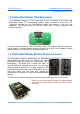
2.1.8 LCD Header
The LCD header (SV3) is connected to the display signals. These are useful to connect
a display other than what is shipped with the development system. For further simplicity,
the pinout of the LCD header is compatible with a color display expansion circuit board
available from www.sparkfun.com
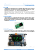
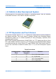
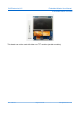
2.1.9 LCD Connector
User can use low cost 128 x 64 1bpp Display similar to the one used in old Embedded
Master Non-TFT Development System. Copper traces for this LCD must face upwards
when inserted in LCD1.The Development System board also exposes all LCD needed
Rev. 2.06 TFT Page 15 of 102 www.ghielectronics.com