Product Technical Specification & Customer Design Guidelines AirPrime MC7304 4114634 Rev 8 Proprietary and Confidential Contents subject to change
Preface Important Notice Due to the nature of wireless communications, transmission and reception of data can never be guaranteed. Data may be delayed, corrupted (i.e., have errors) or be totally lost.
Product Technical Specification & Customer Design Guidelines Patents This product may contain technology developed by or for Sierra Wireless Inc. This product includes technology licensed from QUALCOMM®. This product is manufactured or sold by Sierra Wireless Inc. or its affiliates under one or more patents licensed from InterDigital Group and MMP Portfolio Licensing. Copyright ©2014 Sierra Wireless. All rights reserved.
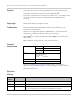
Preface Revision number Release date Changes 4 January 2014 Updated RF block diagram, PCM and I2S audio content, Rx sensitivity (LTE Band 6), general content clarification 5 January 2014 Adjusted GPIO pin names for cross-device consistency 6 January 2014 Removed Draft notice, general cleanup, temperature spec wording changes 7 April 2014 Minor formatting fixes 8 April 2014 Minor formatting fixes Rev 8 Apr.
Product Technical Specification & Customer Design Guidelines 6 Proprietary and Confidential - Contents subject to change 4114634
Contents Introduction . . . . . . . . . . . . . . . . . . . . . . . . . . . . . . . . . . . . . . . . . . . . . . . . . . . . 15 Supported RF bands . . . . . . . . . . . . . . . . . . . . . . . . . . . . . . . . . . . . . . . . . . 15 Physical features . . . . . . . . . . . . . . . . . . . . . . . . . . . . . . . . . . . . . . . . . . . . . 15 Application interface features . . . . . . . . . . . . . . . . . . . . . . . . . . . . . . . . . . . . 16 Modem features . . . . . . . . . . . . . . . . . . . . . . .
Product Technical Specification & Customer Design Guidelines Control interface (Signals) . . . . . . . . . . . . . . . . . . . . . . . . . . . . . . . . . . . . . . 34 WAKE_N — Wake host . . . . . . . . . . . . . . . . . . . . . . . . . . . . . . . . . . . . . . 34 W_DISABLE_N — Wireless disable . . . . . . . . . . . . . . . . . . . . . . . . . . . . 35 WAN_LED_N—LED output . . . . . . . . . . . . . . . . . . . . . . . . . . . . . . . . . . 35 SYSTEM_RESET_N—Reset Input . . . . . . . . . . . . . . . . . .
Contents Power interface . . . . . . . . . . . . . . . . . . . . . . . . . . . . . . . . . . . . . . . . . . . . . . 55 Power ramp-up . . . . . . . . . . . . . . . . . . . . . . . . . . . . . . . . . . . . . . . . . . . . 55 Power-up timing . . . . . . . . . . . . . . . . . . . . . . . . . . . . . . . . . . . . . . . . . . . . 55 Transmit power waveform (GSM) . . . . . . . . . . . . . . . . . . . . . . . . . . . . . . 56 Power supply noise . . . . . . . . . . . . . . . . . . . . . . . . . . . . . . . . . .
Product Technical Specification & Customer Design Guidelines Certification testing . . . . . . . . . . . . . . . . . . . . . . . . . . . . . . . . . . . . . . . . . . . 76 Production testing . . . . . . . . . . . . . . . . . . . . . . . . . . . . . . . . . . . . . . . . . . . . 77 Functional production test . . . . . . . . . . . . . . . . . . . . . . . . . . . . . . . . . . . . . . 77 Production test procedure . . . . . . . . . . . . . . . . . . . . . . . . . . . . . . . . . . . .
List of Tables Table 1-1: Supported RF bands . . . . . . . . . . . . . . . . . . . . . . . . . . . . . . . . . . . . 15 Table 1-2: Modem features . . . . . . . . . . . . . . . . . . . . . . . . . . . . . . . . . . . . . . . . 17 Table 1-3: Required host-module connectors . . . . . . . . . . . . . . . . . . . . . . . . . . 19 Table 2-1: Standards compliance . . . . . . . . . . . . . . . . . . . . . . . . . . . . . . . . . . . 21 Table 3-1: Connector pin assignments . . . . . . . . . . . . . . . . . . . . . .
Product Technical Specification & Customer Design Guidelines Table 5-6: Power-on timing parameters (double enumeration). . . . . . . . . . . . . 56 Table 5-7: Power-on timing parameters (single enumeration) . . . . . . . . . . . . . 56 Table 5-8: Dynamic power control of SAR backoff state. . . . . . . . . . . . . . . . . . 57 Table 7-1: Mechanical and environmental specifications . . . . . . . . . . . . . . . . . 61 Table A-1: Antenna requirements . . . . . . . . . . . . . . . . . . . . . . . . . . . . . .
List of Figures Figure 3-1: System block diagram . . . . . . . . . . . . . . . . . . . . . . . . . . . . . . . . . . . 24 Figure 3-2: Expanded RF block diagram . . . . . . . . . . . . . . . . . . . . . . . . . . . . . . 25 Figure 3-3: SIM application interface . . . . . . . . . . . . . . . . . . . . . . . . . . . . . . . . . 32 Figure 3-4: SIM card contacts (contact view) . . . . . . . . . . . . . . . . . . . . . . . . . . 32 Figure 3-5: Recommended WAKE_N connection . . . . . . . . . . . . . . . . . . . .
Product Technical Specification & Customer Design Guidelines 14 Proprietary and Confidential - Contents subject to change 4114634
1 1: Introduction The Sierra Wireless MC7304 PCI Express Mini Card is a compact, lightweight, wireless LTE- and UMTS-based modem. The MC7304 provides LTE, DC-HSPA+, HSPA+, HSDPA, HSUPA, WCDMA, GSM, GPRS, EDGE, and GNSS connectivity for networking, and M2M applications over several radio frequency bands. The device also supports 2G/3G roaming, subject to network operator provisioning.
Product Technical Specification & Customer Design Guidelines • Temperature · Operating temperature range (Class A): -30°C to +70°C · Operating temperature range (Class B): -40°C to +85°C Important: The internal module temperature must be kept below 100°C. For best performance, the internal module temperature should be kept below 85°C. Proper mounting, heat sinks, and active cooling may be required, depending on the integrated application.
Introduction Modem features Table 1-2: Modem features • LTE/DC-HSPA+/HSPA+/HSPA/UMTS (WCDMA)/EDGE/ GPRS operation • Multiple (up to 16) cellular packet data profiles • Traditional modem COM port support for AT commands • USB suspend/resume • Sleep mode for minimum idle power draw • SIM application tool kit with proactive SIM commands • Enhanced Operator Name String (EONS) • Automatic GPRS attach at power-up • GPRS detach • GPRS detach only • Combined GPRS / IMSI detach; MS-initiated an
Product Technical Specification & Customer Design Guidelines • Dedicated bearer · Network-initiated dedicated bearer · UE-initiated dedicated bearer • Multiple PDN connections (IPv4 and IPv6 combinations), subject to operating system support. (For example, not supported in Windows 8.
Introduction Accessories The Universal Development Kit (UDK) is a hardware development platform for AirPrime MC-series modules. It contains hardware components for evaluating and developing with the module, including: • Development board • Cables • Antennas (Additional antennas may be required to support all bands.
Product Technical Specification & Customer Design Guidelines Integration requirements Sierra Wireless provides, in the document suite, guidelines for successful Mini Card integration and offers integration support services as necessary.
2 2: Standards Compliance The MC7304 Mini Card complies with the mandatory requirements described in the following standards. The exact set of requirements supported is network operator-dependent. Table 2-1: Standards compliance Technology Standards LTE • 3GPP Release 9 UMTS • 3GPP Release 5 • 3GPP Release 6 • 3GPP Release 7 • 3GPP Release 8 GSM/GPRS/EDGE • • Rev 8 Apr.
Product Technical Specification & Customer Design Guidelines 22 Proprietary and Confidential - Contents subject to change 4114634
3 3: Electrical Specifications The system block diagram in Figure 3-1 on page 24 represents the MC7304 module integrated into a host system. The module includes the following interfaces to the host: • Power —Supplied to the module by the host. • W_DISABLE_N —Active low input from a hardware switch to the MC7304 that disables the main RF radio. WAKE_N— Signal used to wake the host when specific events occur.
Product Technical Specification & Customer Design Guidelines RF BLOCK WTR_XO_A0 XO_OUT_A0 RF + GRFC_GPIO EBI2 (NAND) CXO_EN SSBI_PMIC GPIO81 D0_EN XO_OUT_D0_EN PMIC_SSBI PM8018 SSBI PM_MDM_IRQ_N PM_MDM_INT_N MDM9215 VPH/ VBAT KPD_PWR_N EBI1 (DDR DRAM) LED_DRV_N External NAND and RAM 2GB NAND 1GB RAM USIM VCC W_DISABLE_N WAKE_N DPR/GPIO4 ANT_CTRL0/GPIO1 HSUSB ANT_CTRL1/GPIO2 ANT_CTRL2/GPIO3 INTERFACE CONNECTOR WAN_LED_N Figure 3-1: System block diagram 24 Proprietary and Confidenti
Electrical Specifications TX_HB B7 B7 B20 B20 PRX_HB TX_LB1 Main PRX_LB1 B1 PRX_MB3 PRX_MB1 TX_MB4 TX_LB4 SP10T B3 B3 / GSM1800 B1 / B2 / B3 B5 HB B5 / B8 B8 LB PRX_LB3 PRX_LB2 PRX_MB2 TX_LB2 B5 / GSM850 B2 B8 / GSM900 B2 / GSM1900 GSM850/900 LB GSM1800/1900 TX_MB2 HB B5 B5 / B8 Diversity B8 DRX_LB1 DRX_MB DRX_HB SP8T B20 DRX_LB2 B1 B1 / B3 DP6T B3 B2 GNSS B7 GNSS GNSS Bias Circuit Figure 3-2: Expanded RF block diagram Host interface pin assignments The MC7304 ho
Product Technical Specification & Customer Design Guidelines Note: The following table describes the internal structure of the module. Table 3-1: Connector pin assignments 1 Pin Signal name Pin type 2 Description Direction to module Voltage levels (V) Active state Min Typ Max 1 WAKE_N OC Wake host Output Low - - 0.10 2 VCC V Power supply Input Power 3.00 3.30 3.
Electrical Specifications Table 3-1: Connector pin assignments 1 (Continued) Pin Pin Signal name 11 VCC_MSM18_DIG 12 USIM_CLK type 3 2 Description Direction to module Voltage levels (V) Active state Min Typ Max - 1.8V reference voltage output Output Power 1.75 1.80 1.85 - SIM Clock Output Low 0 - 0.45 High 2.40 (3V SIM) - 2.85 (3V SIM) 1.35 (1.8V SIM) 1.90 (1.8V SIM) 13 NC - No connect - - - - - 14 USIM_RST - SIM Reset Output Low 0 - 0.45 High 2.
Product Technical Specification & Customer Design Guidelines Table 3-1: Connector pin assignments 1 (Continued) Pin Signal name I2C_DATA4,5 32 Pin type - 2 Description I2C serial bus data Direction to module Voltage levels (V) Active state Min Input High 1.17 Input Low -0.3 Output High 1.35 Output Low 0.00 Typ 1.80 Max 2.10 0.63 1.80 1.90 0.45 33 SYSTEM_RESET_ N - Reset Input Low -0.30 - 0.
Electrical Specifications Table 3-1: Connector pin assignments 1 (Continued) Pin 46 47 Signal name DPR/ GPIO4 PCM_DOUT/ I2S_DOUT6 Pin type - - 2 Description Direction to module Voltage levels (V) Active state Min Typ Max (DPR) Dynamic power control Input High 1.17 1.80 2.10 Input Low -0.30 - 0.63 (GPIO4) General purpose I/O Input High 1.17 1.80 2.10 Input Low -0.30 Output High 1.35 Output Low 0.00 PCM Data Out/ I2S Data Out Output High 1.35 Output Low 0 0.63 1.
Product Technical Specification & Customer Design Guidelines Power supply The host provides power to the MC7304 through multiple power and ground pins as summarized in Table 3-2. The host must provide safe and continuous power at all times; the module does not have an independent power supply, or protection circuits to guard against electrical issues. Table 3-2: Power and ground specifications Name Pins Specification Min VCC 2, 24, 39, 41, 52 Voltage range See Table 3-1 on page 26.
Electrical Specifications USB high/full speed throughput performance This device has been designed to achieve optimal performance and maximum throughput using USB high speed mode. Although the device may operate with a full speed host, throughput performance will be on an “as is” basis and needs to be characterized by the OEM. Note that throughput will be reduced and may vary significantly based on packet size, host interface, and firmware revision.
Product Technical Specification & Customer Design Guidelines USIM_PWR 4.7uF X5R typ 0.1uF (Optional. Locate near the SIM socket) 15 k - 30 k Located near SIM socket (Optional. Locate near the SIM socket) 47 pF, 51 USIM_CLK (C1) (C3) USIM_DATA (C7) USIM_RST (C2) USIM_GND (C5) SIM card connector AirPrime embedded module Located near SIM socket.
Electrical Specifications SIM implementation Note: For interface design requirements, refer to: (2G) 3GPP TS 51.010-1, section 27.17, or (3G) ETSI TS 102 230 V5.5.0, section 5.2. Rev 8 Apr.14 When designing the remote SIM interface, you must make sure that SIM signal integrity is not compromised.
Product Technical Specification & Customer Design Guidelines Control interface (Signals) The MC7304 provides signals for: • Waking the host when specific events occur • Host control of the module’s radios • LED driver output These signals are summarized in Table 3-5 and paragraphs that follow. Table 3-5: Module control signals Name Pin Description Type 1 WAKE_N 1 Wake host OC W_DISABLE_N 20 Wireless disable (Main RF) PU WAN_LED_N 42 LED driver OC 1.
Electrical Specifications W_DISABLE_N — Wireless disable Note: Wireless disable signals support is optional. The host device uses W_DISABLE_N (pin 20) to enable/disable the WWAN or radio modem. When disabled, the modem cannot transmit or receive information. Letting this signal float high allows the module to operate normally. This switch follows the behavior described in [9] PCI Express Mini Card Electromechanical Specification Revision 1.2. This pin has a 20 k pull-up resistor.
Product Technical Specification & Customer Design Guidelines VCC Current limiting Resistor LED WAN_LED_N MiniCard MIO Figure 3-7: Example LED SYSTEM_RESET_N—Reset Input Note: SYSTEM_RESET_N signal support is optional. SYSTEM_RESET_N has an internal 1.8 V internal pull up. Set this signal to active low to reset the device. Note that the minimum pulse width is 250 ms.
Electrical Specifications PCM The PCM interface implementation details include: • Modes: Master and slave • Sampling rates: 8 kHz, 16 kHz • Audio compression formats: Linear, µ-law, A-Law • Padding: Disabled, enabled • Bits per frame: 8, 16, 32, 64, 128, 256 • Bit frequency: (Sampling rate * Bits per frame) Figure 3-8, Figure 3-9 and Figure 3-10, and Table 3-7 below describe the PCM interface timing.
Product Technical Specification & Customer Design Guidelines Table 3-7: PCM Timing 1 (Continued) Parameter Description Min Typ Max Unit T(sync_offset) PCM_SYNC offset time to PCM_CLK falling - 122 - ns T(sudin) PCM_DIN setup time before falling edge of PCM_CLK 60 - - ns T(hdin) PCM_DIN hold time after falling edge of PCM_CLK 60 - - ns T(pdout) Delay from PCM_CLK rising to PCM_DOUT valid - - 60 ns T(zdout) Delay from PCM_CLK falling to PCM_DOUT HIGH-Z - - 60 ns 1.
Electrical Specifications Antenna control Note: Antenna control signals support is optional. The MC7304 Mini Card provides three output signals that may be used for host designs that incorporate tunable antennas. For details, see [2] AirPrime MiniCard MC73xx/MC8805 AT Command Reference (Doc# 4114486). Table 3-9: Antenna control signals Rev 8 Apr.
Product Technical Specification & Customer Design Guidelines 40 Proprietary and Confidential - Contents subject to change 4114634
4 4: RF Specifications The MC7304 includes three RF connectors for use with host-supplied antennas: • Main RF connector—Rx/Tx path • GNSS connector 1—Dedicated GNSS • Diversity/MIMO connector—Diversity or MIMO The module does not have integrated antennas. Main RF connector GNSS connector Diversity / MIMO I/O connector Figure 4-1: Module connectors RF connections When attaching antennas to the module: Note: To disconnect the antenna, make sure you use the Hirose U.
Product Technical Specification & Customer Design Guidelines Antenna and cabling When selecting the antenna and cable, it is critical to RF performance to optimize antenna gain and cable loss. Note: For detailed electrical performance criteria, see Appendix A: Antenna Specification on page 69.
RF Specifications Ground connection When connecting the module to system ground: • Prevent noise leakage by establishing a very good ground connection to the module through the host connector. • Connect to system ground using the two mounting holes at the top of the module (shown in Figure 4-1 on page 41). • Minimize ground noise leakage into the RF. Depending on the host board design, noise could potentially be coupled to the module from the host board.
Product Technical Specification & Customer Design Guidelines Proximity of host electronics to the antenna in wireless devices can contribute to decreased Rx performance. Components that are most likely to cause this include: • Microprocessor and memory • Display panel and display drivers • Switching-mode power supplies Device-generated RF interference The module can cause interference with other devices.
RF Specifications To determine the extent of any receiver performance desensitization due to selfgenerated noise in the host device, over-the-air (OTA) or radiated testing is required. This testing can be performed by Sierra Wireless or you can use your own OTA test chamber for in-house testing.
Product Technical Specification & Customer Design Guidelines • Inter-RAT and inter-frequency cell reselection and handover between supported frequency bands Table 4-1: LTE frequency band support Band Frequencies Band 1 Tx: 1920–1980 MHz Rx: 2110–2170 MHz Band 3 Tx: 1710–1785 MHz Rx: 1805–1880 MHz Band 7 Tx: 2500–2570 MHz Rx: 2620–2690 MHz Band 8 Tx: 880–915 MHz Rx: 925–960 MHz Band 20 Tx: 832–862 MHz Rx: 791–821 MHz Table 4-2: LTE bandwidth support 1 Band 1.
RF Specifications Table 4-4: GSM frequency band support Band Frequencies GSM 850 Tx: 824–849 MHz Rx: 869–894 MHz EGSM 900 Tx: 880–915 MHz Rx: 925–960 MHz DCS 1800 Tx: 1710–1785 MHz Rx: 1805–1880 MHz PCS 1900 Tx: 1850–1910 MHz Rx: 1930–1990 MHz Conducted Rx sensitivity / Tx power Table 4-5: Conducted Rx (Receive) sensitivity — LTE bands Conducted Rx sensitivity (dBm) LTE bands Primary (Typical) LTE Band 1 Secondary (Typical) SIMO (Typical) SIMO 1 (Worst case) -98.7 -97.8 -101.1 -96.
Product Technical Specification & Customer Design Guidelines Table 4-7: Conducted Rx (Receive) sensitivity — GSM / EDGE bands Conducted Rx sensitivity (dBm) GSM / EDGE bands 2% BER GSM 850 Typical Worst case 1 CS2 -109 -102 GMSK (CS1) -112 -104 EDGE (MCS5) -104 -98 CS2 -109 -102 GMSK (CS1) -112 -104 EDGE (MCS5) -104 -98 CS2 -110 -102 GMSK (CS1) -112 -104 EDGE (MCS5) -105 -98 CS2 -109 -102 GMSK (CS1) -112 -104 EDGE (MCS5) -104 -98 10% BLER 2% BER EGSM 900 10% BLER 2% B
RF Specifications Table 4-8: Conducted Tx (Transmit) power tolerances (Continued) Parameter Conducted transmit power Notes +29 dBm 1 dB GMSK mode, connectorized (Class 1; 1 W, 30 dBm) +26 dBm 1 dB 8PSK mode, connectorized (Class E2; 0.4 W, 26 dBm) DCS1800 CS PCS1900 CS GNSS specifications Note: For detailed electrical performance criteria, see Recommended GNSS antenna specifications on page 71.
Product Technical Specification & Customer Design Guidelines 50 Proprietary and Confidential - Contents subject to change 4114634
5 5: Power Power consumption Power consumption measurements in the tables below are for the MC7304 Mini Card module connected to the host PC via USB. The module does not have its own power source and depends on the host device for power. For a description of input voltage requirements, see Power supply on page 30.
Product Technical Specification & Customer Design Guidelines Table 5-2: Averaged call mode DC power consumption Current 1 Description LTE Notes Max 2 Unit 300 mA 600 3 950 WCDMA HSPA GSM/GPRS EDGE Peak current (averaged over 100 s) mA mA • 68/23 Mbps—0 dBm Tx power • 10 MHz bandwidth • MIMO operation • 68/23 Mbps—20 dBm Tx power • 10 MHz bandwidth • MIMO operation • Worst case • 68/23 Mbps—23 dBm Tx power • All bands • 20 MHz bandwidth 200 mA • 384 kbps at 0 dBm Tx po
Power Table 5-3: Miscellaneous DC power consumption Current / Voltage Signal Description Min USB active current Typ 10 Unit Notes / configuration mA High speed USB connection, CL = 50 pF on D+ and D- signals Max 15 VCC Inrush current Active bias on GNSS port GNSS Signal connector 50 750 2500 mA 75 100 mA 3.3 V Max. voltage output @ 75mA • Assumes power supply turn on time > 100µs • Dependent on host power supply rise time.
Product Technical Specification & Customer Design Guidelines Normal state of module between calls or data connections • Host power source is disconnected from the module and all voltages associated with the module are at 0 V. RF enabled Disconnected • • USB interface active Sleep Details Module is powered State Host is powered Table 5-4: Module power states (Continued) Module cycles between wake (polling the network) and sleep, at network providerdetermined interval.
Power current_vcc < VOLT_LO_WARN current_temp > TEMP_HI_WARN Normal mode current_vcc > VOLT_LO_NORM current_temp < TEMP_HI_NORM current_vcc > VOLT_LO_NORM current_temp <= TEMP_HI_NORM Normal mode Low supply voltage warning or High temperature warning current_vcc < VOLT_LO_CRIT current_temp > TEMP_HI_CRIT current_vcc > VOLT_HI_CRIT current_temp < TEMP_LO_CRIT current_vcc < VOLT_HI_NORM current_temp > TEMP_NORM_LO Low power mode Handled by Power State state machine.
Product Technical Specification & Customer Design Guidelines Table 5-6: Power-on timing parameters (double enumeration) Parameter Typical (s) Maximum (s) t_pwr_on_seq 0.43 0.5 t_USB_active 0.25 0.
Power Power supply noise Noise in the power supply can lead to noise in the RF signal. The power supply ripple limit for the module is no more than 200 mVp-p 1 Hz to 100 kHz. This limit includes voltage ripple due to transmitter burst activity. Additional decoupling capacitors can be added to the main VCC line to filter noise into the device. SED (Smart Error Detection) The module uses a form of SED to track premature modem resets. • Module tracks consecutive resets occuring soon after power-on.
Product Technical Specification & Customer Design Guidelines 58 Proprietary and Confidential - Contents subject to change 4114634
6 6: Software Interface Support tools The MC7304 is compatible with the following support tools from Sierra Wireless and authorized third parties: • Firmware update utilities from Sierra Wireless • Sierra Wireless Logger • QXDM from QUALCOMM • Noise profiling tool • QUALCOMM Product Support Tool (QPST) • Windows and Linux SDKs (including API and drivers) USB interface The device supports the Qualcomm QMI interface.
Product Technical Specification & Customer Design Guidelines 60 Proprietary and Confidential - Contents subject to change 4114634
7: Mechanical and Environmental Specifi- 7 cations The MC7304 module complies with the mechanical and environmental specifications in Table 7-1. Final product conformance to these specifications depends on the OEM device implementation.
Product Technical Specification & Customer Design Guidelines Table 7-1: Mechanical and environmental specifications (Continued) (Electrostatic discharge (See Electrostatic discharge (ESD) on page 64.
Mechanical and Environmental Specifications Figure 7-2: Dimensioned view Labeling MC73XX IMEI # 352678011234569 FPPDDDYNNNNHH BB ||||||||||||||||||||||||||||||||||| FCC ID: N7Nxxxxxx PRODUCT OF CHINA Figure 7-3: Sample unit label Note: The displayed label is an example only. The production label will vary by SKU. The MC7304 label is non-removable and contains: • Rev 8 Apr.
Product Technical Specification & Customer Design Guidelines • IMEI number in Code-128 barcode format • SKU number (when required) • Factory Serial Number (FSN) in alphanumeric format • Manufacturing date code (incorporated into FSN) • Licensed vendor logo • Applicable certification marks/details (e.g. FCC ID, CE information, etc. Example shows FCC ID.) Note: The MC7304 supports OEM partner-specific label requirements.
Mechanical and Environmental Specifications Specific areas requiring heat dissipation are shown in Figure 7-4: • RF—Top and bottom faces of module near RF connectors. Likely to be the hottest area. • Baseband—Top and bottom faces of module, below the RF area. To enhance heat dissipation: • Maximize airflow over/around the module. • Locate the module away from other hot components. • Module mounting holes must be used to attach (ground) the device to the main PCB ground or a metal chassis.
Product Technical Specification & Customer Design Guidelines 66 Proprietary and Confidential - Contents subject to change 4114634
8 8: Regulatory Compliance and Industry Certifications This module is designed to meet, and upon commercial release, will meet the requirements of the following regulatory bodies and regulations, where applicable: • The National Communications Commission (NCC) of Taiwan, Republic of China • Radio Equipment and Telecommunications Terminal Equipment (R&TTE) Directive of the European Union Upon commercial release, the following industry approvals will have been obtained, where applicable: • GCF Addition
Product Technical Specification & Customer Design Guidelines • Near medical equipment, life support equipment, or any equipment which may be susceptible to any form of radio interference. In such areas, the MC7304 modem MUST BE POWERED OFF. Otherwise, the MC7304 modem can transmit signals that could interfere with this equipment. In an aircraft, the MC7304 modem MUST BE POWERED OFF.
A A: Antenna Specification This appendix describes recommended electrical performance criteria for main path, diversity path, and GNSS antennas used with AirPrime embedded modules. The performance specifications described in this section are valid while antennas are mounted in the host device with antenna feed cables routed in their final application configuration. Note: Antennas should be designed before the industrial design is finished to make sure that the best antennas can be developed.
Product Technical Specification & Customer Design Guidelines Table A-1: Antenna requirements (Continued) a Parameter Requirements Total radiated efficiency of Ant1 and Ant2 > 50% on all bands Radiation patterns of Ant1 and Ant2 Nominally Omni-directional radiation pattern in azimuth plane. Envelope correlation coefficient between Ant1 and Ant2 • < 0.4 on 791–894 MHz and 925–960 MHz bands • < 0.2 on 1805–1990 and 2110–2170 MHz bands • < 0.
Antenna Specification Table A-1: Antenna requirements (Continued) a Parameter Requirements Isolation between Ant1 and Ant2 (S21) Power handling > 10 dB • > 2 W RF power on low bands • > 1 W on high bands Comments • If antennas can be moved, test all positions for both antennas. • Make sure all other wireless devices (Bluetooth or WLAN antennas, etc.) are turned OFF to avoid interference.
Product Technical Specification & Customer Design Guidelines Table A-2: GNSS standalone antenna requirements (Continued) Parameter Gain Requirements • Maximum gain and uniform coverage in the high elevation angle and zenith. • Gain in azimuth plane is not desired. Average 3D gain > -5 dBi Isolation between GNSS and Ant1 > 10 dB in all uplink bands Typical VSWR < 2.5:1 Polarization Any other than LHCP (left-hand circular polarized) is acceptable.
B B: Design Checklist This chapter provides a summary of the design considerations mentioned throughout this guide. This includes items relating to the power interface, RF integration, thermal considerations, cabling issues, and so on. Note: This is NOT an exhaustive list of design considerations. It is expected that you will employ good design practices and engineering principles in your integration.
Product Technical Specification & Customer Design Guidelines Table B-1: Hardware integration design considerations (Continued) Suggestion Section where discussed Keep very low capacitance traces on the USIM_DATA and USIM_CLK signals. SIM implementation on page 33 To minimize noise leakage, establish a very good ground connection between the module and host. Ground connection on page 43 Route cables away from noise sources (for example, power supplies, LCD assemblies, etc.).
C C: Testing Note: All AirPrime embedded modules are factory-tested to ensure they conform to published product specifications. Developers of OEM devices integrating Sierra Wireless AirPrime embedded modules should include a series of test phases in their manufacturing process to make sure that their devices work properly with the embedded modules.
Product Technical Specification & Customer Design Guidelines Acceptance test requirements To perform the suggested tests, you require a test system in which to temporarily install the module, and you must be able to observe the test device’s LED indicator. Acceptance test procedure The following is a suggested acceptance testing procedure using Sierra Wireless’ Skylight™ (formerly Watcher™) software: Note: You can perform these tests using appropriate AT commands.
Testing • GCF (Global Certification Forum—www.globalcertificationforum.org) outside of North America • PTCRB (PCS Type Certification Review Board—www.ptcrb.com) in North America Production testing Note: Production testing typically continues for the life of the product. Production testing ensures that, for each assembled device, the module is installed correctly (I/O signals are passed between the host and module), and the antenna is connected and performing to specifications (RF tests).
Product Technical Specification & Customer Design Guidelines • USB connection is functional • LED is functional • W_DISABLE_N (enter low power mode) • Firmware revision check • Rx tests on main and auxiliary paths • Tx test Production test procedure The following is a suggested test plan—you must decide which tests are appropriate for your product. You may wish to add additional tests that more fully exercise the capabilities of your product.
Testing b. Select File > Connection Description. The Connection Description dialog box appears. i. Type Sierra in the Name box and click OK. The Connect To dialog box appears. ii. Click OK without changing any of the displayed information. The Connect dialog box appears. iii. Click Cancel. iv. Type ATZ in the HyperTerminal window. If the connection is established, the message OK appears.
Product Technical Specification & Customer Design Guidelines · (LTE) See LTE RF receive path test on page 84. 15. Test standalone GNSS functionality—See GNSS RF receive path test on page 86. Downloading and configuring minicom for Linux systems Note: This procedure is for Ubuntu systems. If you are using a different Linux distribution, use the appropriate commands for your system to download minicom.
Testing Table C-1: Test settings — UMTS transmission path (Continued) Mode GSM Test category 850 MHz 900 MHz 1800 MHz 1900 MHz Band # GSM850 GSM900 DCS1800 PCS1900 Band ID 18 10 11 12 Tx Channelb 190 65 697 661 2100 MHz n/a a. Either 15 (WCDMA1900A) or 16 (WCDMA1900B) may be used for testing. b. Channel values shown are at the center of the corresponding bands.
Product Technical Specification & Customer Design Guidelines i. Take the measurement. j. AT!DASTXOFF (Turn off the transmitter.) 3. Test limits—Run ten or more good DUTs through this test procedure to obtain a nominal output power value. · Apply a tolerance of 5 to 6 dB to each measurement (assuming a good setup design). · Monitor these limits during mass-production ramp-up to determine if further adjustments are needed.
Testing To test the DUT’s receive path: Note: This procedure describes steps using the Agilent 8648C signal generator—the Rohde & Schwarz SML03 is shown for reference only. 1. Set up the signal generator: a. Set the amplitude to: · -80 dBm (WCDMA mode) · -60 dBm (GSM mode) b. Set the frequency for the band being tested. See Table C-2 on page 82 for frequency values. 2. Set up the DUT: a. AT!ENTERCND (Unlock extended AT command set.) b. AT!DAFTMACT (Put modem into factory test mode.) c.
Product Technical Specification & Customer Design Guidelines · Monitor these limits during mass-production ramp-up to determine if further adjustments are needed. Note: The value measured from the DUT is significantly influenced by the test setup and DUT design (host RF cabling loss, antenna efficiency and pattern, test antenna efficiency and pattern, and choice of shield box). 4. Test diversity paths: Note: Diversity is not available in GSM mode. a. Set up the signal generator as in Step 1.
Testing To test the DUT’s receive path (or diversity path, while connected to the diversity antenna): Note: This procedure describes steps using the Agilent 8648C signal generator—the Rohde & Schwarz SML03 is shown for reference only. 1. Set up the signal generator: a. Set the amplitude to -70 dBm b. Set the frequency for the band being tested. See Table C-3 on page 84 for frequency values. 2. Set up the DUT: a. AT!ENTERCND (Unlock extended AT command set.) b.
Product Technical Specification & Customer Design Guidelines GNSS RF receive path test The GNSS receive path uses the dedicated GNSS connector. To test the GNSS receive path: 1. Inject a carrier signal at -110dBm, frequency 1575.52 MHz into the GNSS Rx path at the connector. (Note that this frequency is 100 kHz higher than the actual GPS L1 center frequency.) 2. Test the signal carrier-to-noise level at the GNSS receiver: a. AT!ENTERCND (Unlock extended AT command set.) b.
Testing • RF sensitivity testing—BER/BLER for different bands and modes • Transmitter and receiver tests (based on relevant sections of the 3GPP TS51010 and 3GPP 34121 documents) Suggested testing equipment To perform production and post-production tests, you will require appropriate testing equipment. A test computer can be used to coordinate testing between the integrated module (on the development kit or host) and the measurement equipment, usually with GPIB connections.
Product Technical Specification & Customer Design Guidelines Table C-4: Extended AT commands Command !SETCND Description Set AT command password Modem reset and status commands !GRESET Reset the modem !GSTATUS Return the operation status of the modem (mode, band, channel, and so on) Diagnostic commands !BAND Select a set of frequency bands or reports current selection !GBAND Read/set the current operating band Test commands 88 !DAFTMACT Put the modem into FTM (Factory Test Mode) !DAFTMDEACT
Testing Table C-4: Extended AT commands Command Rev 8 Apr.
Product Technical Specification & Customer Design Guidelines 90 Proprietary and Confidential - Contents subject to change 4114634
D D: Packaging Sierra Wireless AirPrime Mini Cards are shipped in sealed boxes. The standard packaging (see Figure 4-1), contains a single tray with a capacity of 100 modules. (Note that some SKUs may have custom packaging—contact Sierra Wireless for SKU-specific details.) In the standard packaging, Mini Cards are inserted, system connector first, into the bottom portion (T1) of a two-part tray. all facing the same direction.
Product Technical Specification & Customer Design Guidelines 92 Proprietary and Confidential - Contents subject to change 4114634
E E: References This guide deals specifically with hardware integration issues that are unique to AirPrime embedded modules. Sierra Wireless documents The Sierra Wireless documents listed below are available from www.sierrawireless.com. For additional documents describing embedded module design, usage, and integration issues, contact your Sierra Wireless account representative. Command documents [1] AT Command Set for User Equipment (UE) (Release 6) (Doc# 3GPP TS 27.
Product Technical Specification & Customer Design Guidelines 94 Proprietary and Confidential - Contents subject to change 4114634
F F: Technology Overview LTE LTE (Long Term Evolution) is a 4th-generation wireless standard. The 3GPP Release 8 specification outlines the features and requirements. Key features include. • Peak data rate: · 100 Mbps DL within 20 MHz bandwidth (Peak DL data rate in 10 MHz bandwidth: 70 Mbps (approx.) for Cat 3 device) · 50 Mbps UL within 20 MHz bandwidth Actual throughput depends on the network configuration, bandwidth assigned to the UE, the number of users, and RF signal conditions.
Product Technical Specification & Customer Design Guidelines HSPA HSPA is a third generation (3G) evolution of WCDMA that combines two extensions to UMTS—HSDPA (High Speed Downlink Packet Access) and HSUPA (High Speed Uplink Packet Access). HSPA+ HSPA+ is an enhanced version of HSPA (High Speed Packet Access), as defined by the 3rd Generation Partnership Project (3GPP) Release 7 UMTS Specification for Mobile Terminated Equipment.
Technology Overview • EGPRS—Multislot class 12 (with backoff. See Table F-1 on page 97)—Four Rx slots (maximum), four Tx slots (maximum), five active slots total • All standardized coding schemes (GMSK—CS 1 to CS 4, EDGE—MCS1 to MCS9) Table F-1: EGPRS power backoff Power Backoff (dB) Power class Mode 12 EGPRS GSM850 Band Coding scheme Modulation 1 Time slot 2 Time Slots 3 Time Slots 4 Time Slots MCS1–MCS4 GMSK 0 0 3.5 5.5 MCS5–MCS9 8PSK 0 0 0 0 MCS1–MCS4 GMSK 0 0 2.5 3.
Product Technical Specification & Customer Design Guidelines 98 Proprietary and Confidential - Contents subject to change 4114634
G G: Acronyms Table G-1: Acronyms and definitions Acronym or term Definition 3GPP 3rd Generation Partnership Project 8PSK Octagonal Phase Shift Keying AGC Automatic Gain Control A-GPS Assisted GPS API Application Programming Interface BER Bit Error Rate—A measure of receive sensitivity BLER Block Error Rate bluetooth Wireless protocol for data exchange over short distances CDG CDMA Development Group—a consortium of companies that develop and promote the products and services for CDMA wir
Product Technical Specification & Customer Design Guidelines Table G-1: Acronyms and definitions (Continued) Acronym or term 100 Definition DSM Distributed Shared Memory DUT Device Under Test EDGE Enhanced Data rates for GSM Evolution EIRP Effective (or Equivalent) Isotropic Radiated Power EMC Electromagnetic Compatibility EMI Electromagnetic Interference ERP Effective Radiated Power ESD Electrostatic Discharge FCC Federal Communications Commission The U.S.
Acronyms Table G-1: Acronyms and definitions (Continued) Acronym or term Rev 8 Apr.14 Definition HSPA+ Enhanced HSPA, as defined in 3GPP Release 7 and beyond HSUPA High Speed Uplink Packet Access Hz Hertz = 1 cycle/second IC Industry Canada IF Intermediate Frequency IMEI International Mobile Equipment Identity IMS IP Multimedia Subsystem—Architectural framework for delivering IP multimedia services.
Product Technical Specification & Customer Design Guidelines Table G-1: Acronyms and definitions (Continued) Acronym or term 102 Definition OMA DM Open Mobile Alliance Device Management—A device management protocol. OTA ‘Over the air’ (or radiated through the antenna) PA Power Amplifier packet A short, fixed-length block of data, including a header, that is transmitted as a unit in a communications network.
Acronyms Table G-1: Acronyms and definitions (Continued) Acronym or term Rev 8 Apr.14 Definition SG An LTE signaling interface for SMS (“SMS over SGs”) SIB System Information Block SIM Subscriber Identity Module. Also referred to as USIM or UICC. SIMO Single Input Multiple Output—smart antenna technology that uses a single antenna at the transmitter side and multiple antennas at the receiver side. This improves performance and security.
Product Technical Specification & Customer Design Guidelines Table G-1: Acronyms and definitions (Continued) Acronym or term 104 Definition WAN Wide Area Network WCDMA Wideband Code Division Multiple Access (also referred to as UMTS) WLAN Wireless Local Area Network ZIF Zero Intermediate Frequency Proprietary and Confidential - Contents subject to change 4114634
Index Numerics 3D gain, average gain 3D average (GNSS), 72 3GPP compliance GSM/GPRS/EDGE, 21 LTE, 21 UMTS, 21 A acceptance tests, 75 accessories, 19 accuracy (GNSS), 49 acquisition time (GNSS), 49 acronyms and definitions, 99– 104 A-GNSS, 18 A-GPS, 18 antenna connection considerations, 41 connectors, 23 custom, design, 42 diversity antenna, disabling, 42 GNSS, specifications, recommended, 71 limit, matching coaxial connections, 41 location, considerations, 42 matching, considerations, 42 maximum cable loss
Product Technical Specification & Customer Design Guidelines E H EDGE overview, 96 bands supported, 15 connector, required, 19 electrical specifications, 23 electrostatic discharge specifications, 62 electrostatic discharge.
Index M Q mean effective gain, 70 mean effective gain imbalance, 70 mechanical specifications, 61– 64 MIB, 17 MIMO support, 15 minicom downloading and installing, 80 module power states, 53– 55 QMI interface, 59 QPST (QUALCOMM Product Support Tool), 59 QUALCOMM Product Support Tool (QPST), 59 quality assurance tests, 86 QXDM support, 59 N NAS/AS security, 17 noise leakage, minimizing, 43 RF interference, power supply, 57 O OEM assistance with testing, 87 labeling, 64 operator/carrier testing, 87 order
Product Technical Specification & Customer Design Guidelines sensitivity conducted, RF parameter, 47, 48 defined, 45 radiated measurement, overview, 44 testing, overview, 45 shielding module, compliance, 41 reducing RF desense, 44 shock specifications, 61 SIB, 17 signals, 34 SYSTEM_RESET_N, 36 W_DISABLE_N, 35 WAKE_N, 34 WLAN_LED_N, 35 SIM capacitor recommendations, 33 card contacts, 32 clock rate, 33 connector, required, 19 electrical specifications, 33 impedance, connectors, 33 interface, 31 interface dia
Index Z ZIF (Zero Intermediate Frequency), 43 Rev 8 Apr.