Series 780S Instruction Manual Table of Contents Sierra 780S Series Flat-Trak™ Mass Flow Meter Instruction Manual Part Number IM-78S 07/99 Revision B 5 Harris Court, Building L Monterey, CA 93940 (831) 373-0200 (800) 866-0200 Fax (831) 373-4402 http://www.sierrainstruments.com Sierra Instruments b.v.
Table of Contents Series 780S Instruction Manual Customer Notice Sierra Instruments, Inc. is not liable for any damage or personal injury, whatsoever, resulting from the use of Sierra Instruments standard mass flow meters for oxygen gas. You are responsible for determining if this mass flow meter is appropriate for your oxygen application. You are responsible for cleaning the mass flow meter to the degree required for your oxygen flow application.
Series 780S Instruction Manual Table of Contents Table of Contents Chapter 1 Introduction Series 780S Flat-Trak Mass Flow Meters ..........................1-1 Using this Manual.................................................1-1 Note and Safety Information.....................................1-2 Receipt of System Components .................................1-2 Technical Assistance..............................................1-2 The Series 780S Flow Sensing Principle...........................
Table of Contents Series 780S Instruction Manual Chapter 4 Troubleshooting and Repair Troubleshooting the Flow Meter.....................................4-1 Returning Equipment to the Factory.................................4-3 Appendix A Product Specifications List of Figures 1-1. 2-1. 2-2. 2-3. 2-4. 2-5. 2-6. 2-7. 2-8. 2-9. 2-10. 2-11. 2-12. 2-13. 2-14. 2-15. 2-16. 2-17. 2-18. 2-19. 2-20. 2-21. 2-22. 2-23. 2-24. 3-1. 3-2. 3-3. 3-4. Series 780S Flow Sensing Principle .......................
Series 780S Instruction Manual Table of Contents Warnings and Cautions Warning! Agency approval for hazardous location installations varies between flow meter models. Consult the flow meter nameplate for specific flow meter approvals before any hazardous location installation. Warning! All wiring procedures must be performed with the power off.
Table of Contents 0-6 Series 780S Instruction Manual IM-78S-B
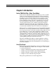
Series 780S Instruction Manual Chapter 1 Introduction Chapter 1 Introduction Series 780S Flat-Trak™ Mass Flow Meters Sierra’s Series 780S Flat-Trak Mass Flow Meter provides a reliable solution for monitoring gas mass flow rate. Low-flow sensitivity, fast response and outstanding rangeability have made this model the instrument of choice for many critical gas flow applications.
Chapter 1 Introduction Series 780S Instruction Manual Note and Safety Information We use note, caution and warning statements throughout this book to draw your attention to important information. Warning! This statement appears with information that is important to protect people and equipment from damage. Pay very close attention to all warnings that apply to your application. Caution! This statement appears with information that is important for protecting your equipment and performance.
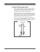
Series 780S Instruction Manual Chapter 1 Introduction The Series 780S Flow Sensing Principle Sierra’s unique Steel-Trak™ sensor probe is responsible for the unsurpassed accuracy, ruggedness and reliability of Sierra industrial flow meters. The immersible Steel-Trak sensor consists of two sensing elements–a velocity sensor and a temperature sensor that automatically corrects for changes in gas temperature.
Chapter 1 Introduction Series 780S Instruction Manual Smart Electronics Features Instrument Validation Two simple tests offer full “field-validation” of your Smart mass flow meter. The first test checks the system electronics, linearization and microprocessor functionality and is performed by injecting a known input value and confirming that the flow meter outputs the expected value.
Series 780S Instruction Manual Chapter 1 Introduction Totalizer With the optional LCD display, actual mass flow appears on line 1 and the totalized flow on line 2 both in the user-specified engineering units. The totalizer counts only the selected range and when ranges are switched, the value of the non-selected range is stored in memory. You may reset the totalizer using the membrane buttons or by using a hand-held magnet.
Chapter 1 Introduction 1-6 Series 780S Instruction Manual IM-78S-B
Series 780S Instruction Manual Chapter 2 Installation Chapter 2 Installation Installation Overview Warning! Agency approval for hazardous location installations varies between flow meter models. Consult the flow meter nameplate for specific flow meter approvals before any hazardous location installation. The Series 780S Flat-Trak™ is available with ANSI or DIN flanges, NPT or butt-weld connections. For ease of installation, the meter is pre-assembled with the sensor probe installed in the flow body.
Chapter 2 Installation Series 780S Instruction Manual Unobstructed Flow Requirements Select an installation site that will minimize possible distortion in the flow profile. Valves, elbows, control valves and other piping components may cause flow disturbances. Check your specific piping condition against the examples shown below. To achieve accurate and repeatable performance, install the flow meter using the recommended number of straight run pipe diameters upstream of the sensor.
Series 780S Instruction Manual Chapter 2 Installation To install the flow meter: Caution! When using toxic or corrosive gases, purge the line with inert gas for a minimum of four hours at full gas flow before installing the flow meter. 1. Turn off the flow of process gas. Verify that the line is not pressurized. Confirm that the installation site meets the minimum upstream pipe diameter requirements shown in Table 2-1. 2. Prepare the fluid connection fittings or flanges in the pipeline.
Chapter 2 Installation Series 780S Instruction Manual Wiring Connections For NEMA 4X enclosures, use TB2 for power and signal connections, TB1 is for sensor connections. (The terminal designations are labeled inside the enclosure cover.) Warning! To avoid potential electric shock, follow National Electric Code safety practices or your local code when wiring this unit to a power source and to peripheral devices. Failure to do so could result in injury or death.
Series 780S Instruction Manual Chapter 2 Installation Input Power Wiring Warning! All wiring procedures must be performed with the power Off. Caution! The AC wire insulation temperature rating must meet or exceed 71°C (158°F). AC Power Wiring The AC power wire size must be 26 to 16 AWG with the wire stripped 1/4 inch (6 mm). Connect 100 to 240 VAC (300 mA load, maximum) to the Neutral and Line terminals on the small, twoposition terminal block. Connect the ground wire to the safety ground lug.
Chapter 2 Installation Warning! All wiring procedures must be performed with the power Off. Series 780S Instruction Manual DC Power Wiring The DC power wire size must be 26 to 16 AWG with the wire stripped 1/4 inch (6 mm). Connect 18 to 30 VDC (625 mA load, maximum) to the terminals marked PWR+ and PWR– on the terminal block. Torque all connections to 4.43 to 5.31 in-lbs (0.5 to 0.6 Nm). All EEx installations must use an approved EEx fitting at both cable entries into the enclosure.
Series 780S Instruction Manual Chapter 2 Installation Output Signal Wiring Output signal cable should be completely screened with a 100% shield. You must use metal cable glands that provide cable screen clamping. The cable screen should be connected to the gland and shielded at both ends over 360 degrees. The shield should be terminated to an earth ground. Flow meters are equipped with either a calibrated 0-5 VDC (0-10 VDC optional) or a calibrated 4-20 mA output signal.
Chapter 2 Installation Series 780S Instruction Manual 4-20 mA Output Wiring The 4-20 mA current loop output can be self-powered (non-isolated) or externally powered (isolated). To use the 4-20 mA isolated output, an external 12 to 36 VDC power supply is required. The maximum loop resistance (load) for both types of current loop outputs are dependent upon the supply voltage and are given in Figure 2-10. Rload is the total resistance in the loop, including the wiring resistance.
Series 780S Instruction Manual Chapter 2 Installation NEMA 4X Enclosures 1 2 Current R load 4-20 out (+) 4-20 out (–) – + 15 16 12 VDC to 36 VDC Figure 2-11. Isolated 4-20 mA Current Loop Connections NEMA 4X Enclosures 1 2 Jumper R load AUX PWR OUT Current 4-20 out (+) V out (–) (Common) 16 15 Figure 2-12.
Chapter 2 Installation Series 780S Instruction Manual Alarm Output Wiring Two alarm outputs (Low Alarm and High Alarm) are included on the flow meter terminal block. The alarm outputs use optical relays that are normally-open single-pole relays with one common connection. There are two connection options for alarm outputs–the first with a separate power supply (isolated) and the second using the flow meter power supply (non-isolated).
Series 780S Instruction Manual Chapter 2 Installation Hazardous-Area Enclosures AC or DC power supply Load ALRM COM Load HI ALARM (–) LO ALARM (–) 1 2 3 4 5 6 7 8 9 10 20 19 18 17 16 15 14 13 12 11 Figure 2-17. Isolated Alarm Output Connections Hazardous-Area Enclosures DC POWER OUT Load Load HI ALARM (–) LO ALARM (–) 1 2 3 4 5 6 7 8 9 10 20 19 18 17 16 15 14 13 12 11 ALRM COM Figure 2-18.
Chapter 2 Installation Series 780S Instruction Manual NEMA 4X Enclosures Remote enclosure Sensor probe RED GREEN Temperature sensor Velocity sensor ORANGE WHITE BLACK Note: Sensor wire color may vary - see label in cover Figure 2-19. Remote Electronics Enclosure to Sensor Connections Figure 2-20.
Series 780S Instruction Manual Chapter 2 Installation Figure 2-22. Sensor Junction Box to Remote Enclosure Connections Range Selection Wiring To access range selection, connect two wires on the terminal strip as shown below. When the switch is closed the device changes to Range 2. Opening the switch returns the device to Range 1. Figure 2-23. Range Selection Wiring Hazardous-Area Enclosures Range 1 1 2 3 4 5 6 7 8 9 10 20 19 18 17 16 15 14 13 12 11 RANGE SELECT COMON Range 2 Figure 2-24.
Chapter 2 Installation 2-14 Series 780S Instruction Manual IM-78S-B
Series 780S Instruction Manual Chapter 3 Operation Chapter 3 Operation This chapter covers flow meter operation, programming and instrument validation procedures. All instructions include directions for using either the optional LCD display or the internal Smart electronics device for programming. If your meter is not equipped with the optional display, you will need a good quality digital voltmeter or multimeter for programming and validation procedures.
Chapter 3 Operation Series 780S Instruction Manual Using the Smart Electronics Basic Features Caution! Before making any adjustment to the Smart electronics device, verify the flow meter is not actively monitoring or reporting to any master control system. Any adjustment to the electronics will cause direct changes to flow control settings.
Series 780S Instruction Manual Chapter 3 Operation LCD Display Programming Menu Start Up Screens Flow meter model Software version Meter serial number Sierra Flow Meter Version Serial No. Run Mode Current flow rate Totalized flow Current range in use User full scale Current flow rate If an alarm is active, will flash LCD Display FUNCTIONS Flow Total Flow Range No.
Chapter 3 Operation Series 780S Instruction Manual Single-Digit LED Programming Menu Run Mode Software version shown in series of 3 digits Version Range in use Range No. 1 Voltage Zero 2 Voltage Span Press FUNCTION to view or change settings. 3 Current Zero Use the UP or DOWN button to enter new parameters. Press FUNCTION to continue.
Series 780S Instruction Manual Chapter 3 Operation Entering Alarm Parameters Caution! The flow meter must not be reporting or measuring gas flow during adjustments. Use the High Alarm and Low Alarm function to set or adjust alarm trip points. The alarms have a minimum hysteresis of 3% to avoid "chattering." When setting a window alarm, the alarm setpoints must be at least twice the hysteresis value apart. We suggest at least a 10% separation between window alarm setpoints.
Chapter 3 Operation Series 780S Instruction Manual K-Factor Adjustment Entering a K-factor adjusts the meter’s output signal without affecting the factory calibration curve. Use the K-factor calibration offset for additional flow profile compensation (the factory includes an initial flow profile correction in the calibration curve of the unit). Caution! The flow meter must not be reporting or measuring gas flow during adjustments. Entering a K-factor using the LCD Display A K-factor value of 1.
Series 780S Instruction Manual Chapter 3 Operation User Full Scale Adjustment Caution! The flow meter must not be reporting or measuring gas flow during adjustments. The user full scale (UFS) feature adjusts the flow meter output range anywhere within 50% to 100% of the factory full scale (FFS). This feature allows you to re-range the voltage or current output of the meter to accommodate different flow rates.
Chapter 3 Operation Series 780S Instruction Manual Time Response Delay Adjustment Changing the Time Response Delay using the LCD Display 1. Select FUNCTION, enter the password. Select FUNCTION again until Time Response appears on the display. 2. Use UP or DOWN to adjust the time response delay from 0.10 to 7.2 seconds. 3. Select FUNCTION again to advance to the next option, or after 12 seconds of non-activity the meter returns to the Run Mode and the new time response setting is in effect.
Series 780S Instruction Manual Chapter 3 Operation Totalizer Reset If your device is equipped with the optional LCD display, reset the totalizer using the magnetic switches or device buttons. If you are unable to open the flow meter enclosure, use a magnet to reset the totalizer as shown below. Reset the Totalizer using the LCD Display 1. Select the desired range. Select FUNCTION, enter the password. Select FUNCTION again until Total Reset? appears on the display. 2.
Chapter 3 Operation 3-10 Series 780S Instruction Manual IM-78S-B
Series 780S Instruction Manual Chapter 3 Operation Using the Smart Electronics Advanced Features Caution! Adjusting zero or span will affect meter calibration. Zero and span (Function 1 through 4) can be used to validate system operation and calibrate the digital to analog signals on the Smart electronics device. Additionally, these functions can compensate for resistance in long signal cables connected to your data collection or indicating system.
Chapter 3 Operation Series 780S Instruction Manual Note: when adjusting zero the current signal will be driven to 4 mA and when adjusting span the current signal will be driven to 20 mA. We recommend recording the current values before making any changes to the current zero or span settings. Current Zero Adjustment If needed, use Zero mA (Function 3) to adjust the 4-20 mA output to 4.0 mA. Caution! Adjusting zero or span will affect meter calibration. 1. Disconnect the 4-20 mA (+) loop wire.
Series 780S Instruction Manual Chapter 3 Operation Instrument Validation System electronics are verified by injecting a known input value and confirming that the flow meter outputs the expected value. This test confirms that the microprocessor, analog to digital and digital to analog converters, the linearizer and the display are working properly.
Chapter 3 Operation Series 780S Instruction Manual Electronics Validation Procedure Caution! Before beginning this procedure, make sure the flow meter is not actively monitoring or reporting to any master control system. Any adjustment to the electronics will cause direct changes to flow control settings. 1. Verify the flow meter is off line from any remote communications. Make sure the meter’s user full scale setting is the same as the factory full scale setting.
Series 780S Instruction Manual Chapter 3 Operation Calibration Certificate Values Sample Point Bridge Voltage Indicated Flow Output (V or mA) Validation Test Results Flow Meter Stated Accuracy Indicated Flow (LCD) Output (V or mA) Flow Meter Stated Accuracy 0% 25% 50% 75% 100% Table 3-1. Electronics Validation Results Sensor Validation Procedure 1. Locate the Ro temperature (measured resistance at 0°C) value and the Alpha value shown on the Calibration Certificate supplied with the flow meter.
Chapter 3 Operation Series 780S Instruction Manual 4. Set the multimeter to read Ohms in the 2K range. Connect the multimeter to the terminals of J5 and J6 (temperature sensor). Measure the resistance between J5 and J6 and record the temperature sensor resistance (in Ohms) in Table 3-2. 5. Set the multimeter to read in the 200 Ohm range. Connect the multimeter to terminals of J7 and J8 (velocity sensor).
Series 780S Instruction Manual Chapter 4 Troubleshooting & Repair Chapter 4 Troubleshooting and Repair Troubleshooting the Flow Meter Begin hardware troubleshooting by verifying the following facilities issues are correct. These areas impact system operation and must be corrected prior to performing any flow meter inspections. Warning! Before attempting any flow meter repair, verify that the line is not pressurized. Always remove main power before disassembling any part of the mass flow meter. 1.
Chapter 4 Troubleshooting & Repair Series 780S Instruction Manual Problem Possible Cause Solution Velocity measurement is erratic or fluctuating Very erratic or non-uniform flow Follow installation requirements shown in Chapter 2 Moisture present in gas flow Install a water trap or filter upstream of the flow meter sensor Flow conditioning plates are not upstream of the sensor Correct flow meter orientation Sensor component broken Return to factory for replacement Malfunction in system electro
Series 780S Instruction Manual Chapter 4 Troubleshooting & Repair Returning Equipment to Factory Before returning any mass flow meter to the factory, you must request and complete a Sierra Calibration/Repair Data Sheet. To obtain the data sheet contact Customer Service at: (800) 866-0200 or (831) 373-0200 in the US or +31(0)20-6145810 in Europe.
Chapter 4 Troubleshooting & Repair 4-4 Series 780S Instruction Manual IM-78S-B
Series 780S Instruction Manual Appendix A Appendix A Specifications Product Specifications Performance Specifications Accuracy ± 2% of reading from 10 to 100% of calibrated range ± 0.5% of full scale below 10% of calibrated range Repeatability ± 0.2% of full scale Temperature Coefficient ± 0.02% of reading per °F within ± 50°F of customer specified conditions ± 0.03% of reading per °F within ± 50°F to 100°F of customer specified conditions ±0.
Appendix A Specifications Series 780S Instruction Manual Leak Integrity 1 X 10⁻⁴ atm cc/sec of helium maximum Power Requirements 18 to 30 VDC (regulated), 625 mA maximum 100 to 240 VAC , 50/60 Hz, 15 watts maximum* *not available on NEMA 4X enclosures Output Signal Linear 0-5 VDC or 0-10 VDC proportional to mass flow rate, 1000 Ohms minimum load resistance, or Linear 4-20 mA proportional to mass flow rate, 700 Ohms maximum resistance (power supply dependent), optically isolated Alarms User-adjustab