
Automobile Parts User's Manual


Chapter 2 Installation Series 780S Instruction Manual
2-4 IM-78S-B
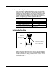
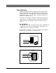
Wiring Connections
For NEMA 4X enclosures, use TB2 for power and signal connec-
tions, TB1 is for sensor connections. (The terminal designations are
labeled inside the enclosure cover.)
Wiring connections
inside cover
To access components:
1. Loosen 4 screws.
2. Remove cover.
NEMA 4X enclosure
terminal blocks
TB1
TB2
1
3
5
7
9
11
13
15
2
4
6
8
10
12
14
16
6
4
2
5
3
1
Figure 2-2. Wiring Access NEMA 4X Enclosures
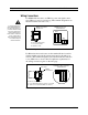
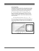
For Hazardous-Area enclosures, use the terminal blocks located in-
side the smaller end of the flow meter enclosure for all wiring con-
nections. (The terminal designations are labeled inside the enclosure
cover.) Make sure to observe all CE compliance requirements for
AC wiring connections given on the next page.
Hazardous-Area enclosure
terminal blocks
Set screw
Wiring
connections
To access components:
1. Use 1/16 inch hex key to loosen set screw.
2. Turn cover counterclockwise to remove.
1
2
3
4
5
6
7
8
9
10
20
19
18
17
16
15
14
13
12
11
Figure 2-3. Wiring Access Hazardous-Area Enclosures
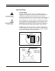
Warning!
To avoid potential electric
shock, follow National Elec-
tric Code safety practices or
your local code when wiring
this unit to a power source
and to peripheral devices.
Failure to do so could result
in injury or death. All AC
power connections must be
in accordance with pub-
lished CE directives.