
Automobile Parts - Air Flow Meter User Manual


Series 24-HP Instruction Manual Chapter 2 Installation
IM-24-HP 2-7
Cold Tap Guidelines
Refer to a standard code for all pipe tapping operations. The following
tapping instructions are general in nature and intended for guideline pur-
poses only.
1. Turn off the flow of process gas, liquid or steam. Verify that the line
is not pressurized.
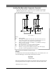
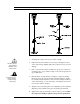
2. Confirm that the installation site meets the minimum upstream and
downstream pipe diameter requirements. See Figure 2-1.
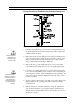
3. Use a cutting torch or sharp cutting tool to tap into the pipe. The pipe
opening must be at least 1.875 inches in diameter. (Do not attempt to
insert the sensor probe through a smaller hole.)
4. Remove all burrs from the tap. Rough edges may cause flow profile
distortions that could affect flow meter accuracy. Also, obstructions
could damage the sensor assembly when inserting into the pipe.
5. After cutting, measure the thickness of the cut-out and record this
number for calculating the insertion depth.
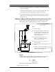
6. Weld the flow meter pipe con-
nection on the pipe. Make sure
this connection is within ± 5°
perpendicular to the pipe cen-
terline.
7. Install the isolation valve (if used).
8. When welding is complete and all fittings are installed, close the
isolation valve or cap the line. Run a static pressure check on the
welds. If pressure loss or leaks are detected, repair the joint and re-
test.
9. Connect the meter to the pipe process connection.
10. Calculate the sensor probe insertion depth as described on the follow-
ing pages. Insert the sensor probe into the pipe.
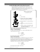
Caution!
When using toxic or
corrosive gases, purge
the line with inert gas
for a minimum of four
hours at full gas flow
before installing the
flow meter.
Warning!
All flow meter connec-
tions, isolation valves
and fittings for cold tap-
ping must have the same
or higher pressure rating
as the main pipeline.