
Automobile Parts - Air Flow Meter User Manual


Chapter 2 Installation Series 24-HP Instruction Manual
2-20 IM-24-HP
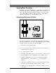
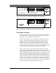
4-20 mA Output Connections
The standard Innova-Mass Flow Meter has a single 4-20 mA loop. Two
additional loops are available on the optional communication board. The
4-20 mA loop current is controlled by the meter electronics. The electron-
ics must be wired in series with the sense resistor or current meter. The
current control electronics require 12 volts at the input terminals to oper-
ate correctly.
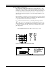
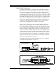
The maximum loop resistance (load) for the current loop output is depend-
ent upon the supply voltage and is given in Figure 2-16. The 4-20 mA loop
is optically isolated from the flow meter electronics.
R
load
is the total resistance in the loop, including the wiring resistance
(R
load
= R
wire
+ R
sense
). To calculate R
max
, the maximum R
load
for the loop,
use the maximum loop current, 20 mA. The voltage drop in the loop due
to resistance is 20 mA times R
load
and this drop is subtracted from the in-
put voltage. Thus:
The maximum resistance R
load
= R
max
= 50
*
(V
supply
– 12V).
Figure 2-16. Load Resistance Versus Input Voltage
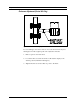
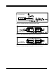
Figure 2-17. Isolated 4–20 mA Output with External Power Supply