
Automobile Parts - Air Flow Meter User Manual
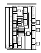
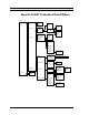

Series 24-HP Instruction Manual Appendix E MODBUS Commands
IM-24-HP E-5
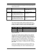
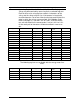
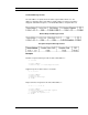
The following registers contain the display units strings:
Registers Variable Data type Units Function code Addresses
32007-32012 Volume flow units string — 03, 04 2006-2011
32001-32006 Mass flow units string — 03, 04 2000-2005
32025-32030 Temperature units string — 03, 04 2024-2029
32019-32024 Pressure units string
—
03, 04 2018-2023
32031-32036 Density units string — 03, 04 2030-2035
32013-32017 Energy flow units string — 03, 04 2012-2017
Function codes 03 (read holding registers) and 04 (read input regis-
ters) are the only codes supported for reading these registers, and
function codes for writing holding registers are not implemented.
We recommend that the floating point and long integer registers be
read in a single operation with the number of registers being a mul-
tiple of two. If these data are read in two separate operations, each
reading a single 16-bit register, then the value will likely be invalid.
The floating point registers with values in display units are scaled
to the same units as are displayed, but are instantaneous values
that are not smoothed. If display smoothing is enabled (non-zero
value entered in the Display TC item in the Display Menu), then
the register values will not agree exactly with the displayed val-
ues.
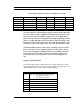
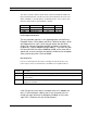
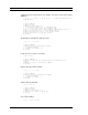
Exception Status Definitions
The Read Exception Status command (function code 07) returns the exception
status byte, which is defined as follows. This byte may be cleared by setting “coil”
register #00003 (function code 5, address 2, data = 0xff00).
Bit(s) Definition
0-1 Byte order (see Modbus Order on page 2)
0 = 3-2:1-0 1 = 2-3:0-1
2 = 1-0:3-2 3 = 0-1:2-3
2 Temperature sensor fault
3 Pressure sensor fault
4 A/D converter fault
5 Period overflow
6 Pulse overflow
7 Configuration changed