Series 820 Instruction Manual Table of Contents Sierra 820 Series Top-Trakª Mass Flow Meters Instruction Manual Part Number IM-82 Revision C 06-99 5 Harris Court, Building L Monterey, CA 93940 (831) 373-0200 (800) 866-0200 Fax (831) 373-4402 http://www.sierrainstruments.com Sierra Instruments b.v.
Table of Contents Series 820 Instruction Manual Customer Notice Sierra Instruments, Inc. is not liable for any damage or personal injury, whatsoever, resulting from the use of Sierra Instruments standard mass flow meters or controllers for oxygen gas. You are responsible for determining if this mass flow meter or controller is appropriate for your oxygen application. You are responsible for cleaning the mass flow meter or controller to the degree required for your oxygen flow application.
Series 820 Instruction Manual Table of Contents Table of Contents Chapter 1 Introduction Introduction.............................................................1-1 Using this Manual .................................................1-1 Safety Information.................................................1-2 Receipt of System Components..................................1-2 Technical Assistance ..............................................1-2 Top Trak Features................................................
Table of Contents Series 820 Instruction Manual Appendix A Conversion Formulas and Gas Tables Appendix B Production Specifications List of Figures 1-1. 1-2. 1-3. 2-1. 2-2. 2-3. 2-4. 2-5. 2-6. 4-1. 4-2. 4-3. 4-4. 4-5. 4-6. 4-7. 0-4 Top-Trak Features (Typical)..................................1-3 Flow Paths through the Transducer..........................1-4 Flow Measuring Principle.....................................1-4 Piping Requirements for 1/2-inch Size Connections.......
Series 820 Instruction Manual Table of Contents Cautions Caution! Only qualified personnel should install the transducer. Caution! Do not supply +DC power at the D-connector while using a power supply at the power jack. Both supplies may be damaged. Caution! Operating a 12 VDC transducer at 24 VDC will cause equipment damage. Caution! Only qualified personnel should perform transducer service, calibration or troubleshooting procedures.
Table of Contents 0-6 Series 820 Instruction Manual IM-82-C
Series 820 Instruction Manual Chapter 1 Introduction Chapter 1 Introduction This instruction manual covers the installation, operation and maintenance of SierraÕs 820 Series product line including the following Top-Trakª Models: · 822 Mass Flow Meter with display (nylon flow body) · 824 Mass Flow Meter without display (nylon flow body) · 826 Hi-Flow Meter with display (aluminum flow body) · 827 Hi-Flow without display (aluminum flow body) · 822-S Mass Flow Meter with display (stainless steel flow body) ·
Chapter 1 Introduction Series 820 Instruction Manual Safety Information Caution and warning statements are used throughout this book to draw your attention to important information. Warning! Caution! This statement appears with information that is important to protect people and equipment from damage. Pay very close attention to all warnings that apply to your application. This statement appears with information that is important for protecting your equipment and performance.
Series 820 Instruction Manual Chapter 1 Introduction Top-Trak Features Standard Top-Trak Mass Flow Meters require a 12 to 15 VDC external power source (24 VDC input power optional). The transducerÕs 0 to 5 VDC output signal allows for flow recording, data-logging or control. A 4 to 20 mA output signal is optionally available. Input power and output signal connections are made via the 9-pin sub-type D-connector located on the side of the transducer.
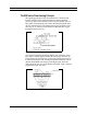
Chapter 1 Introduction Series 820 Instruction Manual The 820 Series Flow Sensing Principle The operating principle of Top-Trak transducers is based on heat transfer and the first law of thermodynamics. During operation process gas enters the instrumentÕs flow body and divides into two flow paths, one through the sensor tube, the other through the laminar flow element bypass.
Series 820 Instruction Manual Chapter 2 Installation Chapter 2 Installation Installation Overview To ensure a successful installation, inlet and outlet tubing should be clean and free from burrs or rims caused by cutting prior to plumbing the transducer into the system. The protective caps covering the inlet/outlet fittings should not be removed until immediately prior to installation. Before installing the transducer, verify the following: 1.
Chapter 2 Installation Series 820 Instruction Manual Installing the Transducer Caution! Only qualified personnel should install the transducer. Follow the installation instructions that apply to your transducer’s process connection. For all 1/2-inch size process connections, observe the piping recommendations given on page 2-3. Before operation, all plumbing should be checked carefully for leaks and the transducer purged with dry nitrogen. Compression Fittings 1.
Series 820 Instruction Manual Chapter 2 Installation 1/4 Inch Female NPT (standard on nylon flow bodies) 1. Position the transducer with the flow direction arrow pointing downstream in the direction of flow. 2. Use a good quality paste pipe thread sealant. Apply to the pipe threads. 3. Tighten the pipe no more than 1 turn past hand-tight. Caution! Do not over-tighten, damage to the instrument may result. 4. Check the system’s entire flow path thoroughly for leaks.
Chapter 2 Installation Series 820 Instruction Manual Wiring the Transducer Caution! Do not supply +DC power at the D-connector while using a power supply at the power jack. Both supplies may be damaged. Standard Top-Trak™ transducers require a 12 to 18 VDC power supply (15 VDC nominal, 100 mA maximum). 24 VDC input power is optional. Transducers are connected to the power supply through either the dedicated DC power jack or through the 9-pin D-connector located on the side of the enclosure.
Series 820 Instruction Manual Chapter 2 Installation Standard 0-5 VDC Output Signal Wiring The standard 0-5 VDC output signal flows from Pin 3 (0-5 VDC Out) through the load (1K Ohm minimum) to Pin 7 (Power Common). The figure below is a typical example of input power and output signal connections. Figure 2-3.
Chapter 2 Installation Series 820 Instruction Manual Figure 2-5. Multiple Transducer Current Loop Connections Remote Display Installation Mount the remote display at a convenient location within reach of the supplied interface cable. The maximum cable length is 100 feet (30 m). Figure 2-6.
Series 820 Instruction Manual Chapter 3 Operation Chapter 3 Operation The output signal of the transducer is either 0-5 VDC (standard) or 4-20 mA (optional). The output signal is linear and proportional to the gas mass flow rate. For example, for a 0-5 VDC output signal, 5.00 VDC is the output signal for the full scale listed on the transducer’s nameplate, 2.50 VDC is for one-half of full scale, and 0.00 VDC is for zero flow. For a 4-20 mA output signal, 20.
Chapter 3 Operation Series 820 Instruction Manual Referencing the Transducer to Non-Standard Conditions The gas flow rate output of your transducer is referenced to “standard” conditions of 21°C (70°F) and 760 mm of mercury (1 atmosphere) unless otherwise specified on the certificate of calibration. Check the stated reference conditions of your transducer.
Series 820 Instruction Manual Chapter 3 Operation Zero and Span Adjustments The zero and span potentiometers are accessed through the ports marked on the side of the transducer. Normally, span adjustments are not made unless you are calibrating the transducer. The span adjustment should not be used unless you have a known, precise nonzero flow rate that you wish to match.
Chapter 3 Operation 3-4 Series 820 Instruction Manual IM-82-C
Series 820 Instruction Manual Chapter 4 Maintenance & Repair Chapter 4 Maintenance and Repair Caution! It is important that this transducer be serviced and/or calibrated by qualified personnel. Top-Trak™ transducers essentially require no scheduled maintenance other than periodic flow path cleaning if the gas is dirty. If an in-line filter is used, the filtering element should be periodically replaced or ultrasonically cleaned.
Chapter 4 Maintenance & Repair Series 820 Instruction Manual Flow Path Cleaning Model 822/824 Figure 4-1. Model 822/824 Flow Components Inlet and Outlet Screens 1. Remove the transducer from the system. Caution! When using toxic or corrosive gases, purge the unit thoroughly with inert dry gas before disconnecting from the gas line. 1. Remove inlet and outlet fittings. 2. Pull out the laminar flow element (LFE) holddowns. 3. Replace or clean the inlet and outlet screens. 4. Re-assemble components.
Series 820 Instruction Manual Chapter 4 Maintenance & Repair Laminar Flow Element The laminar flow element (LFE) is a precision flow divider which diverts a preset amount of flow through the sensor tube. The LFE is made of precision machined 316 stainless steel. The particular LFE used depends on the gas and flow range of the instrument. To clean or inspect the LFE: Caution! When using toxic or corrosive gases, purge the unit thoroughly with inert dry gas before disconnecting from the gas line. 1.
Chapter 4 Maintenance & Repair Series 820 Instruction Manual Flow Path Cleaning Model 826/827 Laminar Flow Element The laminar flow element (LFE) is a precision flow divider which diverts a preset amount of flow through the sensor tube. The particular LFE used depends on the gas and flow range of the instrument. To clean or inspect the LFE: Caution! When using toxic or corrosive gases, purge the unit thoroughly with inert dry gas before disconnecting from the gas line. 1.
Series 820 Instruction Manual Chapter 4 Maintenance & Repair Flow Path Cleaning Model 822-S/824-S Laminar Flow Element The laminar flow element (LFE) is a precision flow divider which diverts a preset amount of flow through the sensor tube. The LFE is made of precision machined 316 stainless steel. The particular LFE used depends on the gas and flow range of the instrument.
Chapter 4 Maintenance & Repair Series 820 Instruction Manual Figure 4-5. Medium Flow Transducer LFE Cleaning Medium Flow Transducers: In the medium flow body, the LFE assembly consists of the honeycomb laminar flow element, inlet screen, 0.63 inch long standoff, two ranging washers, 2-1⁄4 inch long 4-40 screw and 4-40 nut. Range changes in the honeycomb element are made with various diameter ranging washers.
Series 820 Instruction Manual Chapter 4 Maintenance & Repair Figure 4-6. High Flow Transducer LFE Cleaning High Flow Transducers: The high flow LFE is similar to the honeycomb element used in the medium flow body but larger in diameter. The high flow body consists of four parts: inlet tube, inlet cap, main flow body and end cap. The inlet tube is only removed to inspect and replace the sealing O-ring between the inlet tube and inlet cap.
Chapter 4 Maintenance & Repair Series 820 Instruction Manual Sensor Cleaning and Inspection Due to sensor design variations, the following sensor cleaning instructions are for Model 822-S/824-S only. All other transducer models must be returned to the factory. Sensor cleaning is accomplished by simply rodding out the sensor with the Sensor Cleaning Stylette, part number “CK” available from Sierra. A 0.028 inch diameter piano wire may also be used.
Series 820 Instruction Manual Chapter 4 Maintenance & Repair Transducer Calibration Caution! It is important that this transducer be calibrated only by qualified personnel. Calibration of Sierra’s flow meters requires a calibration standard of at least four times the accuracy of the transducer. Sierra’s Cal-Bench Automated Primary Calibration System is the preferred method of calibration and is used at the factory for all calibrations from 10 sccm up to 50 slpm.
Chapter 4 Maintenance & Repair Series 820 Instruction Manual Step 4. Adjusting Linearity First gain access to the printed circuit board inside the enclosure: 1. For units with the digital display, carefully rotate the display until it hits the top plate. Slide the display’s two side panels up and remove. Move the display aside taking care not to damage the connecting cable. 2. Remove the two Phillips head screws from the top of the transducer enclosure.
Series 820 Instruction Manual Chapter 4 Maintenance & Repair Transducer Troubleshooting When you suspect that the transducer is not operating correctly, there are a few simple checks that can be made before taking the unit out of service: 1. Make certain that there are no leaks in the gas line. 2. Check that all cables are connected and are in good condition. 3. Verify that the power supply is in the correct range and properly connected to the transducer. 4.
Chapter 4 Maintenance & Repair Series 820 Instruction Manual Returning Equipment to the Factory Factory Calibration—All Models Sierra Instruments maintains a fully-equipped calibration laboratory. All measuring and test equipment used in the calibration of Sierra transducers are traceable to NIST Standards. Sierra is ISO-9001 registered and conforms to the requirements of ANSI/NCSL-Z540 and ISO/IEC Guide 25.
Series 820 Instruction Manual Chapter 4 Maintenance & Repair RETURN ADDRESS: Caution! Always fully neutralize any toxic gas trapped inside the instrument before removing it from the gas line. Sierra Instruments, Inc. Attention: Factory Service Center 5 Harris Court, Building L Monterey, CA 93940 USA CUSTOMER SERVICE AND SUPPORT INFORMATION: Email Technical Support: service@sierrainstruments.com Email Sales: sales@sierrainstruments.
Series 820 Instruction Manual Appendix A Appendix A Conversion Formulas and Gas Tables Conversion of Flow Rate to Other T and P Conditions The flow rate of your transducer is referenced to certain ÒstandardÓ conditions of temperature and pressure. Unless otherwise specified in your order, these standard conditions are 21°C (70°F) and 760 mm of mercury (1 atmosphere).
Appendix A Series 820 Instruction Manual Calculating For a Single Gas The following tables provide K-factors and thermodynamic properties of gases commonly used with mass flow meters and controllers. The purpose of these tables is two-fold: 1. Calibrating an ÒactualÓ gas with a reference gas. This is particularly useful if the actual gas is not a common gas or if it is toxic, flammable, corrosive, etc. 2.
Series 820 Instruction Manual Appendix A Where: H = The constant amount of heat applied to the sensor tube, ¥ = The mass flow rate of the gas (gm/min) m Cr = The coefficient of specific heat of the gas (Cal/gm); Cr is given in the Table (at 0°C), DT = The temperature difference between the downstream and upstream coils, and N = A correction factor for the molecular structure of the gas given by the following table: Number of Atoms in the Gas Molecule Monatomic Diatomic Triatomic Polyatomic N 1.040 1.
Appendix A Series 820 Instruction Manual For our purposes, we want the ratio of the flow rate, Q1, for an actual gas to the flow rate of a reference gas, Q2, which will produce the same output voltage in a particular mass flow meter or controller. We get this by combining equations (1) and (5): Q1/Q2 = K1/K2 = (N1/ r1Cp1)/(N2/r2CP2) (6) Please note that the constant b cancels out. Equation (6) is the fundamental relationship used in the accompanying tables.
Series 820 Instruction Manual Appendix A Calculating Dual Gas Mixtures Equation (6) is used for gas mixtures, but we must calculate N/rCp for the mixture.
Appendix A Series 820 Instruction Manual Gas Tables and K-factors Actual Gas Acetylene Air Allene (Propadiene) Ammonia Argon Arsine Boron Trichloride Boron Trifluoride Bromine Boron Tribromide Bromine Pentafluoride Bromine Trifluoride Bromotrifloromethane (Freon-13 B1) 1,3-Butadiene Butane 1-Butane 2-Butane 2-Butane Carbon Dioxide Carbon Disulfide Carbon Monoxide Carbon Tetrachloride Carbon Tetrafluoride (Freon-14) Carbonyl Fluoride Carbonyl Sulfide Chlorine Chlorine Trifluoride Chlorodifluoromethane (Fre
Series 820 Instruction Manual Actual Gas Dichloromethylsilane Dichlorosilane Dichlorotetrafluoroethane (Freon-114) 1,1-Difluoroethylene (Freon-1132A) Dimethylamine Dimethyl Ether 2,2-Dimethylpropane Ethane Ethanol EthylAcetylene Ethyl Chloride Ethylene Ethylene Oxide Fluorine Fluoroform (Freon-23) Freon-11 Freon-12 Freon-13 Freon-13 Freon-14 Freon-21 Freon-22 Freon-113 Freon-114 Freon-115 Freon-C318 Germane Germanium Tetrachloride Helium Hexafluoroethane (Freon-116) Hexane Hydrogen Hydrogen Bromide Hydroge
Appendix A Actual Gas Methyl Mercaptan Methyl Trichlorosilane Molybdenum Hexafluoride Monoethylamine Monomethylamine Neon Nitric Oxide Nitrogen Nitrogen Dioxide Nitrogen Trifluoride Nitrosyl Chloride Nitrous Oxide Octafluorocyclobutane (Freon-C318) Oxygen Difluoride Oxygen Ozone Pentaborane Pentane Perchloryl Fluoride Perfluoropropane Phosgene Phosphine Phosphorous Oxychloride Phosphorous Pentafluoride Phosphorous Trichloride Propane Propylene Silane Silicon Tetrachloride Silicon Tetrafluoride Sulfur Dioxi
Series 820 Instruction Manual Appendix B Specifications Appendix B Product Specifications Operating Specifications Gases Most gases; check compatibility with wetted materials; specify when ordering Mass Flow Rates Models 822/824: 0 to 10 sccm to 0 to 50 slpm; Models 826/827: 0 to 75 slpm to 0 to 175 slpm; Models 822-S/824-S: 0 to 10 sccm to 0 to 500 slpm; flow ranges specified are for an equivalent flow of nitrogen at 760 mm Hg and 21°C (70°F); other ranges in other units are available (e.g.
Appendix B Specifications Series 820 Instruction Manual Performance Specifications Accuracy ±1.5% of full scale including linearity over 15 to 25°C and 5 to 60 psia (0.3 to 4 bara) Repeatability ±0.5% of full scale Temperature Coefficient 0.08% of full scale per °F (0.15% of full scale per °C), or better Pressure Coefficient 0.01% of full scale per psi (0.
Series 820 Instruction Manual IM-82-C Appendix B Specifications B-3
Appendix B Specifications B-4 Series 820 Instruction Manual IM-82-C