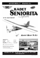
SPECIFICATIONS Wing Span: 65 in. Wing Area: 800 sq. in. Length: 54.7 in. Flying Weight: 4.8 - 5.0 lbs. Wing Loading: 13.8 - 114.4 oz./sq.ft. (1651 mm) (51.6 dm²) (1389 mm) (2177 - 2268 g) (42-44 g/dm2) Radio: 4-Channel with 4 Standard Servos Electric Power: Brushless Outrunner Motor (400-700w; 700-1000kv; 35-42 mm case dia.) 45-75A Speed Control (ESC) 3-4s 3000-4000 mah Lipo Battery Pack SIG MFG. CO., INC. PO Box 520 Montezuma, IA 50171-0520 www.sigmfg.com © Copyright 2015, SIG Mfg Co., Inc.
ELECTRIC POWER RECOMMENDATIONS ❑ 600 - 700 watt BRUSHLESS OUTRUNNER MOTOR The KADET SENIORITA SPORT is designed for brushless outrunner electric motors rated for approximately 400 to 700 watts output. While this range is quite wide, it illlustrates the versatility of the KADET's light wing loading. This airplane can fly with minimal power for realistic flight, or with extra power for load carrying chores and more aerobatic performance.
Dremel® Tool With Selection of Sanding & Grinding Bits Scissors Sandpaper Heat Iron & Trim Seal Tool Masking Tape Paper Towels Alcohol and/or Acetone For Epoxy Clean-up for your particular motor. Make sure the ESC is designed for a "brushless" motor. Most ESCs suitable for the KADET SENIORITA will also have a built-in BEC (Battery Eliminator Circuit). Important Note: BEC allows you to use the same battery pack to power both your motor and your radio system, eliminating the normal radio battery pack.
Once your iron is set to the correct temperature, go over the entire framework of the airplane, making sure that the covering is securely bonded to the structure everywhere the covering comes in contact with the wood underneath. This takes some time, but is worth the effort. After you have all the covering secured onto the solid areas, turn the temperature of the iron up to approximatelly 300OF - 320OF (149OC - 160OC). This is the correct temperature for shrinking the covering material.
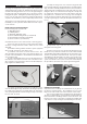
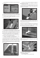
f) Untape the string at the root end of the wing panel and begin carefully pulling the string and the aileron chord through the wing You will occasionally feel like the wire has become stuck inside the wing. This is simply the plug on the end of the servo wire hitting the side of one of the holes in the wing ribs. Gently work the string back and forth from both ends until the plug slips through the hole.
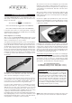
b) When dry, mount the control horn in position on the bottom of the aileron with the screws. Do the same for the other aileron. b) Now carefully insert the exposed portion of the three hinges into the trailing edge of the wing. You will find it easiest to slide the hinges into the slots at angle, one hinge at a time, instead of trying to push it straight onto all the hinges at once. c) Adjust the aileron so that the tip of the aileron is flush with the wing tip.
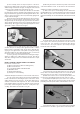
g) Once the ailerons are properly adjusted, insure that the metal clevis can’t open up and come loose from the control horn by sliding the piece of Fuel Tubing over the arms of the clevis. Also tighten the M2 Hex Nut up against the back of the clevis. spacing of the wheel in the wheel pant. Tighten the wheel collar set screw securely. ❑ 8) Slide the wheel on the axle and test to make sure it spins freely on the axle. Next slide one of the Main Wheels onto the axle and test to make sure it spins freely.
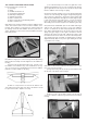
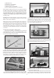
c) Use a fine line felt tip pen to mark some guide lines on the stabilizer that will make it easy for you to realign the stab after the glue is applied in the next step. You can now remove the pins and take the stabilizer off the fuselage for gluing. TAIL SURFACE & TAILWHEEL INSTALLATION For the following steps you will need: (1) Fuselage (1) Wing (1) Stabilizer & Elevator set (1) Vertical Fin & Rudder Set (2) M6.
e) Finish the rudder installation by gluing the CA Hinges in place with Thin CA, using the same techniques you did for the aileron hinges back in Step 2. f) After all the glue is dry, adjust the wheel collar to sit snug against the bottom of the nylon tailwheel bearing. The purpose of the wheel collar is to keep any loads from the tailwheel from putting stress on the rudder. c) Keep sliding the wire in until the short top leg exits the slot in the stabilizer.
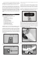
(2) Metal RC Clevis (2) small pieces of Fuel Tubing (2) Pushrod Snap Keepers (1) Radio Receiver (not furnished) (2) Servos with Mounting Screws (not furnished) ❑ 21) Install the rudder and elevator servos inside the fuselage in the built-in plywood radio mounting tray. Note that the rudder servo goes on the left side of the airplane, and the elevator servo goes on the right side. (The servo opening in the front right side of the tray is for the throttle servo in a glow installation.
* The “thrust washer” is the part of the prop adaptor where the back of the propeller will be located. tighten the M2 Hex Nut up against the back of the clevis b) Subtract the measurement taken in the previous step a) from 4.2”. The result is the distance you need to locate the front of the firewall from the back of the plywood motor mount box. Carefully measure and mark the distance determined from the back edge of the motor mount box towards the front.
b) Decide on a good location to mount the ESC. The most likely place in the KADET SENIORITA is in the top of the nose, above the plywood battery tray. Use a plastic cinch strap to secure it to the airplane structure. c) Now route the ESC’s servo wire back to the receiver and plug it in. d) Connect the ESC's motor wires to the motor. Operate the motor and check the direction of rotation.
❑ 33) COOLING IS IMPORTANT! With a fully cowled motor, it is very important to make sure your power system is getting proper cooling. Air flowing into the front of the cowling must have a place to exit the cowl. In fact it’s best to have more air exit area than inlet area to create a positive air flow through the cowling - an actual suction effect - drawing the heated air out of the cowling so that more cool air can come in. This positive air flow keeps your motor running cool.
Place your fingertips within the balance range on both sides of the airplane and carefully lift it off the table. No part of the model should be touching anything except your fingertips! If the KADET SENIORITA will sit on your fingertips in a level attitude, then it is properly balanced and ready to fly. FLYING The KADET SENIORITA is designed to give you the best possible chance to succeed in learning to fly R/C. However, learning to fly model airplanes is not a skill you can learn overnight.
It’s not that learning to fly R/C is difficult, it’s just a lot different than anything you have ever done before. Anyone can learn to fly the KADET SENIORITA if they are willing to listen and learn! Remember the first time you tried to ride a bicycle? It seemed completely awkward the first time, but once you learned how, it quickly became very easy. Learning to fly R/C model airplanes also comes quickly to many people. Fly your KADET SENIORITA as often as possible.
CUSTOMER SERVICE SIG MFG. CO., INC. is committed to your success in both assembling and flying the KADET SENIOR SPORT ARF. Should you encounter any problem building this kit or discover any missing or damaged parts, please feel free to contact us by mail or telephone. SIG MFG. CO., INC. P.O. Box 520 401 South Front Street Montezuma, IA 50171-0520 USA PHONE: 1-641-623-5154 FAX: 1-641-623-3922 SIG WEB SITE: www.sigmfg.com SIG E-MAIL: mail@sigmfg.com SIG MFG CO., INC. Copyright 2015 SIG MFG CO., INC. 401 S.