
SIGRC19EPARFB-Manual
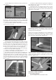

g) Once the ailerons are properly adjusted, insure that the
metal clevis can’t open up and come loose from the control horn
by sliding the piece of Fuel Tubing over the arms of the clevis.
Also tighten the M2 Hex Nut up against the back of the clevis.
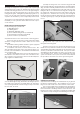
❑ 5) Test fit the two finished wing panels together with the Alu-
minum Front Wing Joiner Blade and the Steel Rear Wing Joiner
Pin. Then test fit the wing assembly on the fuselage. The tab
that is formed by the two panels at the center, leading edge, fits
into the cutout in the front fuselage former. At the rear, two M6.5
nylon wing bolts secure the wing to the fuselage. If you encounter
any difficulties mounting the wing to the fuselage, find the problem
and fix it now. Then remove the wing from the fuselage and set it
aside.
INSTALL THE MAIN LANDING GEAR
Locate the following parts from the kit contents:
(1) Fuselage
(1) Aluminum Main Landing Gear
(3) M4 x 20 mm Socket-Head Bolts
(3) M4 Flat Washers
(2) 2-1/2" dia. Main Wheels
(2) 4 mm dia. Threaded Axles
(4) 5 mm Hex Nuts; for axles
(4) 4 mm ID Wheels Collars; for axles
(1) Right Fiberglass Wheel Pant
(1) Left Fiberglass Wheel Pant
(4) M3 x 10 mm Socket-Head Bolts
NOTE: We suggest you use a thread locking liquid (like Locktite®)
on all bolts and nuts used in the assembly of the landing gear.
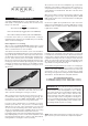
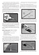
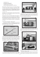
❑ 6) Install a Threaded Axle into the large hole of the landing gear
leg, with the plain end of the axle shaft pointing to the outside.
Secure the axle with the 7.6mm Hex Nut. When tightening the
nut, keep the flats of the hex nut on the axle side of the gear leg
parallel to the front edge of the leg - see photo. This allows the
hex nut to fit inside the narrow notch in the wheel pants when they
are added later.
❑ 7) Slide a 4mm Wheel Collar onto the axle shaft, but leave ap-
proximately 1/8” of space between it and the nut, to provide proper
spacing of the wheel in the wheel pant. Tighten the wheel collar
set screw securely.
❑ 8) Slide the wheel on the axle and test to make sure it spins
freely on the axle. Next slide one of the Main Wheels onto the
axle and test to make sure it spins freely. If it does not turn freely,
drill out the plastic hub of the wheel with an 11/64" or #17 drill bit.
❑ 9) Slide a second wheel collar onto the axle and up to the
wheel. Leave a small gap between it and the wheel, so the wheel
will turn freely, and then tighten the wheel collar set screw.
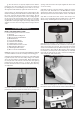
❑ 10) Check the orientation of the landing gear to make sure you
know which way is forward. The two outer holes for mounting the
gear to the fuselage go to the front. Then test fit the wheel pants
over the wheels and line up the predrilled mounting holes. Secure
the wheel pants in place with two M3 x 10mm socket head bolts
for each pant. (You may need to clean a little paint out of the blind
nuts inside the wheel pants in order to start the mounting bolts.
A #11 hobby knife works well for this.)
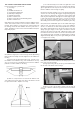
❑ 11) Attach the landing gear to the bottom of the fuselage using
three M4 x 20mm Socket-Head Bolts and three M4 Flat Washers.
7
FUSELAGE ASSEMBLY